© 2023 Carrier 22
OPERATING CONTROL FUNCTIONS
1. Operating Controls: Pressure or temperature activated, the operating control closes,
causing the burner start-up sequence to begin. When the operating control opens, the
burner shuts off. The operating control is connected in the L1-3 circuit on the wiring
base.
2. Limit Switches: These are pressure, water level or temperature activated
a. Recycle — To stop the burner when the limit switch opens and restart it when the
limit switch recloses, recycle limit switches connected between Terminals L1 and 3.
b. Non-Recycle —when it is necessary to stop the burner when the limit switch opens
and prevent it from starting until both the limit switch recloses and the manual reset is
activated, they are connected between terminals 3 and P.
3. Fuel Valve End Switch Interlock: This is an integral switch mounted on the main fuel
valve and activated by the valve stem. It is connected between Terminal L1 & 13. The
fuel valve end switch interlock prevents a burner start-up if the valve stem is not in the
“valve closed” position. This interlock must remain closed while in STANDBY and until
the start of PTFI.
4. Purge Interlock: A firing rate motor linkage position switch or a differential air-
pressure switch that proves a maximum purge air flow rate. It is connected between
Terminals M and 8. The purge interlock proves that the air damper is fully open and
purge air flow rate is at maximum during the purge.
5. Running Interlocks: These are air flow switches, high and low fuel pressure switches,
oil temperature switches, atomizing media pressure switches, and excess smoke density
controls. These interlocks prove proper conditions for normal operation of the burner.
They are wired in series and connected between Terminals 3 and P. (For YP148/YP184
programmers, connected between Terminals L1 and P).
6. Low Fire Start Interlock: A firing rate motor linkage position switch or a damper
position switch, proves both the linkage and dampers are in their proper positions to
begin burner light off. This switch is connected between Terminals M and D.
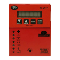
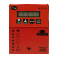
SETTING PROGRAMMER PARAMETERS
To change the factory default parameters stored in the programmer module an optional
keypad/dis-play (BLV512 or BLL510) is required. All configurable parameters are stored
within the PROGRAM SETUP sub-menu. The keypad/display module provides tactile
feedback keys that are used to access the sub-menus inherent in the BurnerLogix system.
The BurnerLogix display has 2 lines with 16 characters per line. The default display top line
shows the current operating status. This includes the current point in the burner sequence
followed by the parameter pertaining to that point in the sequence, such as time or the flame
signal level. The bottom line displays the current operating status. The BurnerLogix display
also provides the historical information stored in the control’s memory such as burner hours,
cycles, lockouts, and system hours. The remainder of the display items are menus with sub-
menus indicated by a right facing arrow >. The sub-menus indicate the current value of the
selected item and in some cases can be modified to suit the application.
 Loading...