© 2023 Carrier 29
WIRING - UV SCANNERS
To connect the scanner to the control, the UV1A Scanner is supplied with either 36"(.9m) or 72" (1.8m)
of flexible cable. The 45UV5 is supplied with four 72” (1.8m) lead wires. Install them in a suitable length
of flexible armor cable and connect it to the control. A conduit connector is supplied with the scanner.
Connect black wires (shutter) to terminals L1, L2; red wires (UV tube) to terminals S1, S2.
If it is necessary to extend the scanner wiring, the following instructions apply:
Scanner wires should be installed in a separate conduit. The wires from several scanners may be installed
in a common conduit.
1. Selection of Wire
a. Wiring: For extended scanner wiring up to 500 feet, and for shorter lengths to reduce
signal loss, use a shielded wire (Belden 8254-RG62 coaxial cable, or equal) for each
scanner wire of UV1A, UV2 and each red wire of the 45UV5. The ends of the
shielding must be taped and not grounded.
b. Asbestos insulated wire must be avoided.
c. Multiconductor cable is not recommended without prior factory approval.
2. High voltage ignition wiring must not be installed in the same conduit with flame detector wires.
INSTALLATION—INFRARED SCANNER TYPE 48PT2
Where possible, obtain the burner manufacturer’s instructions for mounting the scanner, otherwise
proceed as follows:
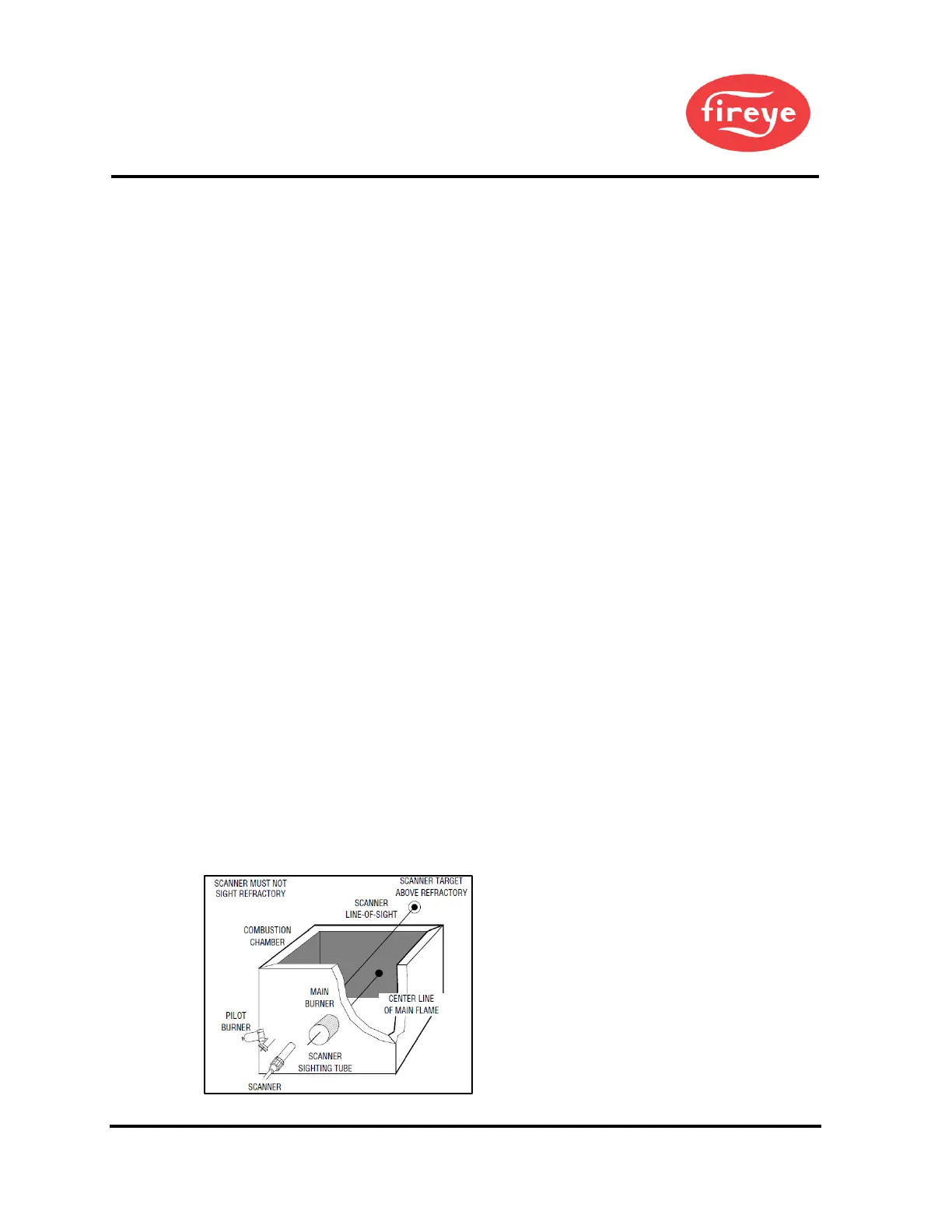
A single scanner is used to detect both pilot and main flames. The sight pipe on which the scanner mounts
must be aimed so that the scanner sights a point at the intersection of main and pilot flames.
Proper scanner positioning must assure the following:
1. Reliable pilot flame signal.
2. Reliable main flame signal.
3. A pilot flame too short or in the wrong position to ignite the main flame reliably,
must not be detected.
4. Scanner must have an unobstructed view of flame being monitored.
5. Flame being monitored must completely cover the scanner field of view.
6. To avoid nuisance shutdowns, it is important to avoid sighting hot refractory and to keep
scanner temperature below 140° F (60°C).
7. When the proper position has been established, drill a hole through the furnace wall and
install a 4" to 8" (101.6mm x 203.2mm) length of threaded l/2" black iron pipe on which to mount
the 48PT2 scanner.
8. When satisfactory sighting position has been confirmed by operating tests, the sight tube
should be firmly welded in place.
Figure 11. SCANNER INSTALLATION
 Loading...