© 2023 Carrier 14
INSTALLATION PROCEDURE
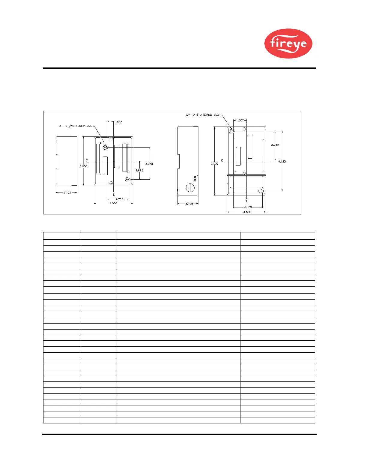
WIRING BASE
Select either the terminal block style (60-2812-1, 60-2814-1). Either wiring base type can be mounted on
a din rail or directly mounted to the cabinet back plate. Refer to Figure 2 for mounting dimensions.
Figure 2. WIRING BASE DETAILS
The location should be free from excessive vibration and within the ambient temperature rating.
Table 11: PRE-WIRED WIRING BASE, P/N 60-2810-1 (shown for 120 VAC)
120/230 VAC (+10%,-15%), 50/60 Hz
300 VAC, 3 mA (UV models only)
300 VAC, 3 mA (UV models only)
120/230 VAC, 1 A pilot duty
120/230 VAC, 9.8 FLA, 58.8 LRA
Fuel Valve End Switch, Pre-Ignition Interlock
Open Damper Proving Switch
Delayed Main Valve YP300 programmer only
See Load Ratings (Page 7)
Ignition (Applies to YP148, YP184 programmers only)
See Load Ratings (Page 7)
See Load Ratings (Page 7)
Pilot Valve (Applies to YP148, YP184 programmers only)
See Load Ratings (Page 7)
See Load Ratings (Page 7)
Main Valve 1 (Applies to YP148, YP184 programmers only)
See Load Ratings (Page 7)
See Load Ratings (Page 7)
Main Valve 2 (Applies to YP148, YP184 programmers only)
See Load Ratings (Page 7)
Fuel Selection (Applies to YP148, YP184 programmers only)
Low Gas Pressure Switch (Applies to YP148, YP184 programmers only)
Valve Prove Switch (Applies to YP148, YP184 programmers only)
UL does not apply to 230 VAC operations
HEIGHT WITH CONTROL INSTALLED IS 5.8" (147MM)
 Loading...