© 2023 Carrier 68
VALVE PROVING
The Burnerlogix offers an intelligent Valve Proving System (VPS). It checks the effective
closure of automatic shut-off valves by measuring the pressure differential between two fuel
shutoff valves during the test sequence. When active, it will open and close the main safety
shutoff valves (double block valve arrangement) in the proper sequence and monitor the
pressure in the gas pipe between the two safety shutoff valves (MV1 & MV2).
The gas pressure sensing device, pressure switch, is recommended to be installed between the
two shutoff valves. Follow the below method of pressure switch setup as described below:
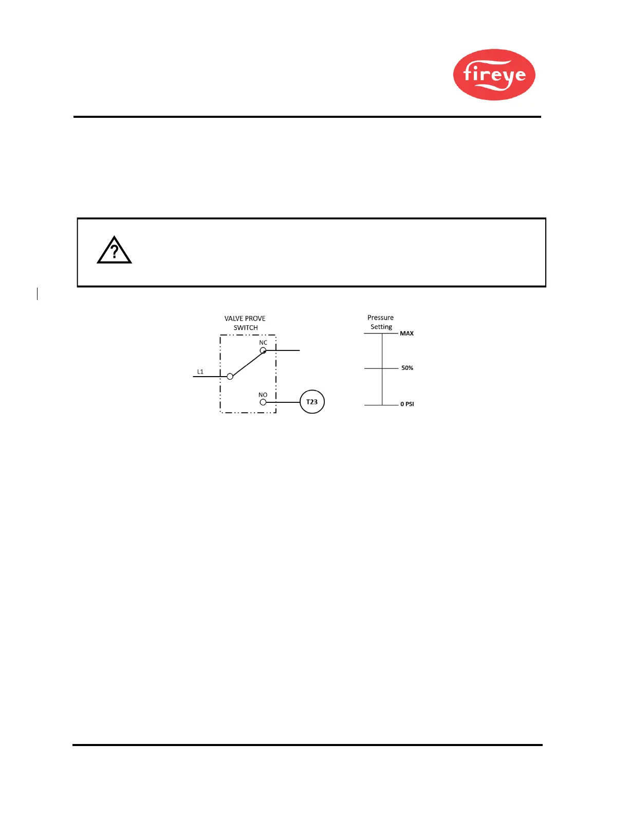
A single pressure switch installed between the shutoff valves. This setup requires that the gas
pressure switch be adjusted to ½ the gas train pressure. The rule of operation is quite simple:
The pressure switch will "make" (T23 high) when gas pressure in the test section exceeds the
set pressure; it will "break" (T23 low) when the gas pressure falls below the set pressure.
Pressure Switch Selection
1. Determine the maximum inlet pressure for the upstream valve.
2. For above method, divide the inlet pressure by 2 (50%) and select a gas pressure switch that
will trip at the halfway point. For adjustable type pressure switches, adjust the setting to the
desired trip point.
Proper hookup and connection of Terminal 23 is required in order to properly operate the valve
proving feature. The Burnerlogix is designed to allow valve proving to be performed at the
beginning or at the end of a burner cycle. Burnerlogix supports valve proving for 2-valve
system only. The 2-valve system is a setup with an upstream and downstream shutoff valve
and the test gas is evacuated into the combustion chamber.
During the valve proving operation, the test section of the gas train is pressurized and
evacuated in a methodical fashion. During the test sequence, the Burnerlogix allows the test
section to be pressurized for 3 seconds and evacuated for 3 seconds. The pressurization or
evacuation time cannot be adjusted. It is recommended that qualified personnel make the
adjustments to the TEST times at the burner standby state.
WARNING: It is the responsibility of the installing and operating personnel to ensure that
the valve proving system is properly installed and configured. The appropriate permissible
leakage rate information should be used when setting up a valve proving system.
Please consult the burner manufacturer and/or applicable codes, ordinances, and regulations.
 Loading...