© 2023 Carrier 74
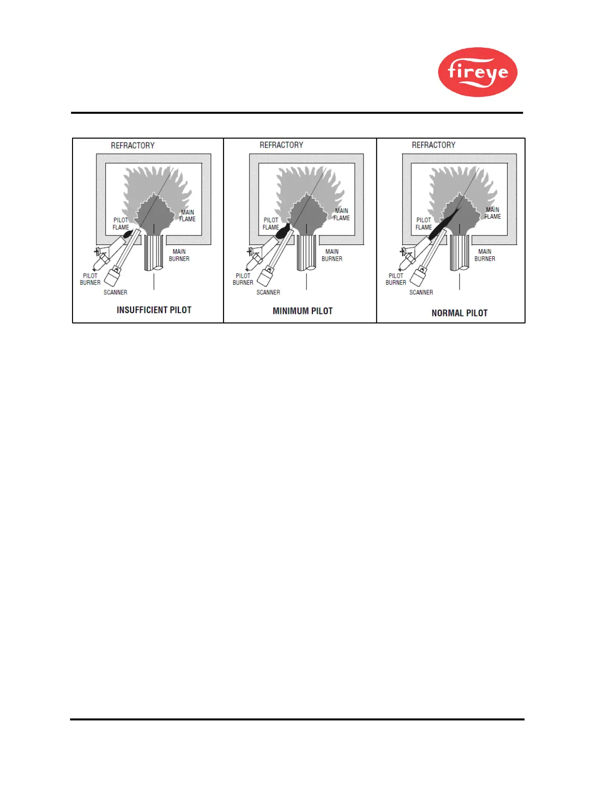
Figure 32. PILOT FLAME TEST
Scanner Wiring
Take care to see that ignitor cables and scanner cables are routed away from one another on all
installations. These cables, when crossed or run together, may interfere with the proper
operation of the Burnerlogix control.
If you are experiencing erratic operation or inappropriate characters on the display during the
trial for ignition period, the cause is likely to be ignitor noise. Check for worn ignitor
cable insulation, broken, or cut insulation or loose connectors at the electrode and
transformers.
BURNERLOGIX GROUNDING RULES
The BurnerLogix system, is microprocessor based and requires a ground system that provides a
zero-voltage reference. The voltage measured from L2 to all other terminals except L1
should be 0 volts.
1. The most effective ground is to run the ground wire in the same raceway as the hot and
neutral from the main distribution service panel (not intermediate sub-panels) to the
burner control panel and ensure that this ground wire is well bonded to the control panel.
2. The wiring base of the BurnerLogix must have earth ground providing a connection
between the sub-base and the control panel or the burner.
3. The earth ground wire must be capable of conducting the current to blow the 20A fuse
in event of an internal short circuit. A number 14 AWG copper conductor is adequate,
wide straps or brackets are preferred rather than lead wires.
4. The ground path needs to be low impedance (less than 1 ohm) to the equipment frame
which in turn needs a low impedance to earth ground. For a ground path to be low
impedance at RF frequencies, the connection must be made with minimum length
conductors having maximum surface areas.
5. All connections should be free of nonconductive coatings and protected against rust.
6. Utilizing conduit as a means of providing a ground must be avoided.
7. Installing ground rods at the burner control panel defeats the purpose of a single point
ground as described above and could also present a safety hazard.
 Loading...