© 2023 Carrier 34
Notes:
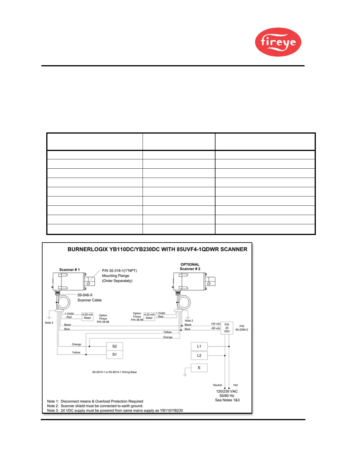
1. Flame relay contacts are shown in the de-energized (no flame condition).
2. Fault relay contacts are shown in de-energized (fault) condition.
3. BMS = Burner Management System (by others). Do not use Red as 24-volt ground.
4. External 2.0 Amp fuses recommended.
5. A safety ground screw is provided on the scanner end plate. An external ground
wire must be installed if line voltage is applied to the relay contacts.
Table 16: PHOENIX SCANNER CABLE COLOR CODE
NEW 59-546 CABLE COLOR CODE
(Connector Pin No.)
OLD 59-497 CAPTIVE-CABLE COLOR CODE
For reference only
Flame Relay Contact (n.o.)
Flame Relay Contact (n.o.)
Fault Relay Contact (n.c.)
Fault Relay Contact (n.c.)
4-20 ma Analog Output (+)
4-20 ma Analog Output (-)
Figure 13. BURNERLOGIX TYB110DC/YB230DC WITH 85UVF4-1QDWR SCANNER
 Loading...