© 2023 Carrier 27
INSTALLATION - UV SCANNERS
Where possible, obtain the burner manufacturer’s instructions for mounting the scanner.
This information is available for most standard burners. The scanner mounting must comply
with the following general instructions:
1. Position the UV1A, UV2 scanner within 30 inches of the flame to be monitored; the
45UV5 within 72 inches, closer if possible.
2. Select a scanner location that remains within the ambient temperature limits of the UV
Scanner. If cooling is required, use an insulating coupling (Fireye #35-69 for UV1A,
UV2 Scanners, #35127-1 for 45UV5) to reduce conducted heat.
3. The UVlA, UV2, 45UV5 Scanners are designed to seal off the sight pipe up to 1 PSI
pressure. Higher furnace pressures should be sealed off. To seal off positive furnace
pressure up to 100 PSI for UV1A, UV2 Scanners, install a quartz window coupling
(#60-1257) For 45UV5 Scanners, use #60-1100 coupling. Add cooling air to reduce the
scanner sight pipe temperature.
4. Install the scanner on a standard NPT pipe (UV1A: 1/2", UV2: 3/8", 45UV5: 1") whose
position is rigidly fixed. If the scanner mounting pipe sights through the refractory, do not
extend it more than halfway through. Swivel flanges are available if desired (#60-302 for
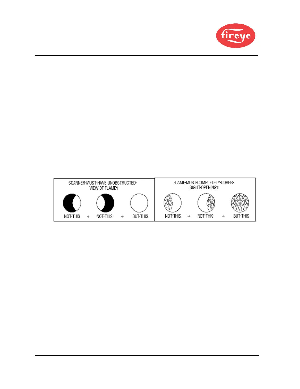
UV1A, UV2 Scanners, #60-1664-3 for 45UV5). The sight pipe must permit an
unobstructed view of the pilot and/ or main flame, and both pilot and main flames must
completely cover the scanner field of view.
Figure 8. AIMING YOUR SCANNER
5. Smoke or unburned combustion gases absorb ultra-violet energy. On installations with
negative pressure combustion chambers, a small hole drilled in the UV1A, UV2 sight
pipe will assist in keeping the pipe clean and free from smoke. Provide clean air to
pressurize the sight pipe, if necessary, for positive pressure furnaces.
6. Two UV1A or UV2 Scanners may be installed on the same burner if it is necessary to
view two areas to obtain reliable detection of the flame. They are wired in parallel. Only
one repetitive self-checking 45UV5 Scanner can be installed on a burner.
7. To increase scanner sensitivity with UV1A, UV2 Scanners, a quartz lens permits
location of the scanner at twice the normal distance. Use l/2" x 1 l/2" pipe nipple between
UV1A Scanner and the coupling. Use 3/8" pipe nipple and a l/2" x 3/8" bushing on UV2
installations.
8. Request the assistance of any Fireye field office for recommendations of a proper
scanner installation on a non-standard application.
 Loading...