Instruction Manual
D103412X012
Detailed Setup—PID Function Block
July 2013
141
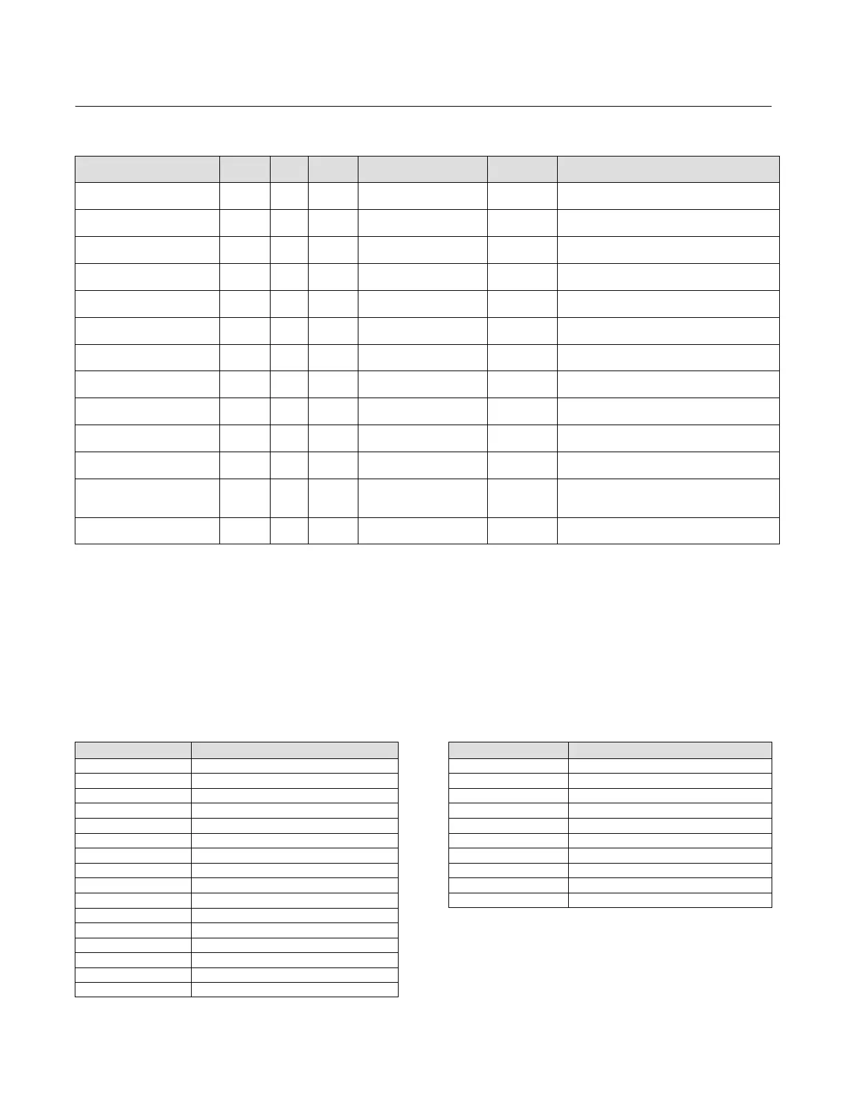
Table 4‐32. PID Function Block System Parameters Definitions (Continued)
DescriptionInitial ValueRange
Block
Mode
RO /
RW
Index
Number
Label
PARAMETER_NAME
T Ipgain
T_IPGAIN
80 RO N/A 0.0
Data Type: Float
Integrated process gain.
T Ugain
T_UGAIN
81 RO N/A 0.0
Data Type: Float
Ultimate gain.
T Uperiod
T_UPERIOD
82 RO N/A 0.0
Data Type: Float
Ultimate period.
T Psgain
T_PSGAIN
83 RO N/A 0.0
Data Type: Float
Process static gain.
T Ptimec
T_PTIMEC
84 RO N/A 0.0
Data Type: Float
Process time constant.
T Pdtime
T_PDTIME
85 RO N/A 0.0
Data Type: Float
Process dead time.
T Targetop
T_TARGETOP
86 ALL 2
Data Type: Unsigned8
Target oscillation periods.
T Hyster
T_HYSTER
87 ALL > = 0.0 0.0
Data Type: Float
Hysteresis
T Relayss
T_RELAYSS
88 ALL > = 0.0 3.0
Data Type: Float
Relay step size.
T Gain Magnifier
T_GAIN_MAGNIFIER
89 ALL > 0.1, < 100 1.0
Data Type: Float
Scales amount of gain.
T Auto Extra DT
T_AUTO_EXTRA_DT
90 ALL 0
Data Type: Unsigned8
Allow additional cycle with extra deadtime.
T Auto Hysteresis
T_AUTO_HYSTERESIS
91 ALL 0
Data Type: Unsigned8
Allows calculation of hysteresis based on
CAP_STDDEV
T Aoperiods
T_AOPERIODS
92 RO N/A 0
Data Type: Unsigned8
Actual oscillation periods.
View Lists
View lists allow the values of a set of parameters to be accessed at the same time. Views 1 and 2 contain operating
parameters and are defined by the Fieldbus Foundation. View 3 contains dynamic parameters and View 4 contains
static parameters with configuration and maintenance information. Views 3 and 4 are defined by the manufacturer.
Table 4‐33. PID Function Block, View 1
Index Number Parameter
1 ST_REV
5.1 MODE_BLK.TARGET_MODE
5.2 MODE_BLK.ACTUAL_MODE
5.3 MODE_BLK.PERMITTED_MODE
5.4 MODE_BLK.NORMAL_MODE
6 BLOCK_ERR
7 PV
8 SP
9 OUT
18 CAS_IN
38 TRK_IN_D
39 TRK_VAL
45.1 ALARM_SUM.CURRENT
45.2 ALARM_SUM.UNACKNOWLEDGED
45.3 ALARM_SUM.UNREPORTED
45.4 ALARM_SUM.DISABLED
Table 4‐34. PID Function Block, View 2
Index Number Parameter
1 ST_REV
10 PV_SCALE
11 OUT_SCALE
12.1 GRANT_DENY.GRANT
12.2 GRANT_DENY.DENY
17 BYPASS
21 SP_HI_LIM
22 SP_LO_LIM
28 OUT_HI_LIM
29 OUT_LO_LIM
 Loading...


