Instruction Manual
D103412X012
Detailed Setup—ISEL Function Block
July 2013
157
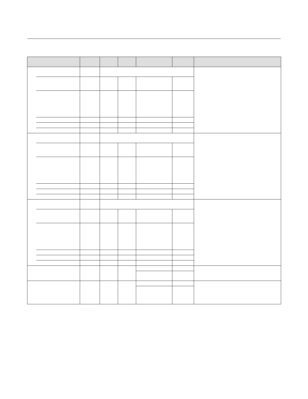
Table 4‐40. Input Selector Function Block Parameter Definitions (Continued)
Description
Initial
Value
Range
Block
Mode
RO / RW
Index
Number
Label
PARAMETER_NAME
High Alarm
HI_ALM
46
Data Type: DS‐71
The high alarm data, which includes a value of the
alarm, a timestamp of occurrence, and the state of the
alarm.
UNACKNOWLEDGED 46.1 RW N/A
0=Undefined
1=Acknowledged
2=
Unacknowledged
0
ALARM_STATE 46.2 RO N/A
0=Undefined
1=Clear reported
2=Clear not reported
3=Active reported
4=Active not
reported
0
TIME_STAMP 46.3 RO N/A 0
SUBCODE 46.4 RO N/A 0
VALUE 46.5 RO N/A 0
Low Alarm
LO_ALM
47
Data Type: DS‐71
The low alarm data, which includes a value of the
alarm, a timestamp of occurrence, and the state of the
alarm.
UNACKNOWLEDGED 47.1 RW N/A
0=Undefined
1=Acknowledged
2=
Unacknowledged
0
ALARM_STATE 47.2 RO N/A
0=Undefined
1=Clear reported
2=Clear not reported
3=Active reported
4=Active not
reported
0
TIME_STAMP 47.3 RO N/A 0
SUBCODE 47.4 RO N/A 0
VALUE 47.5 RO N/A 0
Low Low Alarm
LO_LO_ALM
48
Data Type: DS‐71
The low low alarm data, which includes a value of the
alarm, a timestamp of occurrence, and the state of the
alarm.
UNACKNOWLEDGED 48.1 RW N/A
0=Undefined
1=Acknowledged
2=
Unacknowledged
0
ALARM_STATE 48.2 RO N/A
0=Undefined
1=Clear reported
2=Clear not reported
3=Active reported
4=Active not
reported
0
TIME_STAMP 48.3 RO N/A 0
SUBCODE 48.4 RO N/A 0
VALUE 48.5 RO N/A 0
Output Discrete
OUT_D
49
MAN
OOS
Status
Data Type: DS‐66
Discrete output to indicate a selected alarm value
Value
0, 1
Alarm Select
ALM_SEL
50 ALL
Status
Data Type: Bit String
Used to select the process alarm conditions that will
cause the OUT_D parameter to be set.
1: Hi Hi
2: Hi
3: Lo Lo
4: Lo
All bits:0
View Lists
View lists allow the values of a set of parameters to be accessed at the same time. Views 1 and 2 contain operating
parameters and are defined by the Fieldbus Foundation. View 3 contains dynamic parameters and View 4 contains
static parameters with configuration and maintenance information. Views 3 and 4 are defined by the manufacturer.
 Loading...


