Instruction Manual
D103412X012
Detailed Setup—DI Function Block
July 2013
203
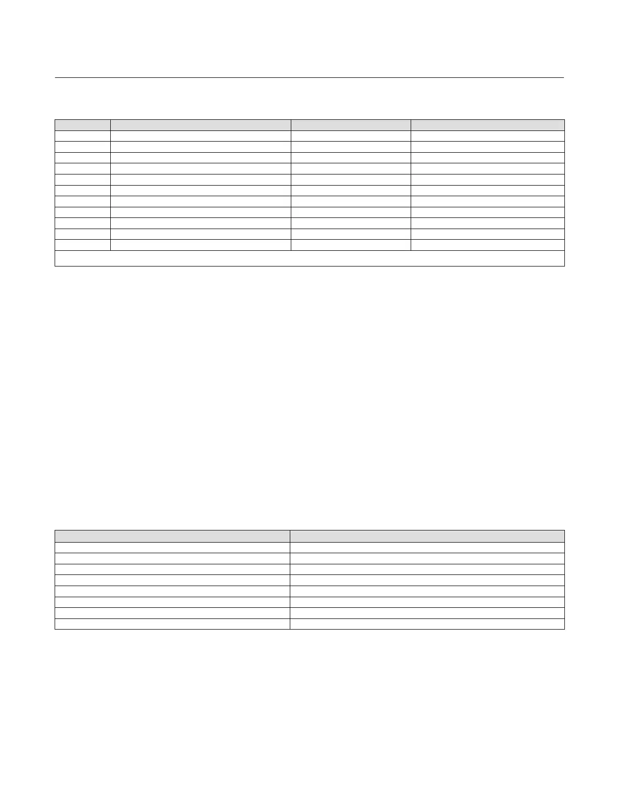
Table 4‐77. Channel Selection for the Discrete Input Function Block
Selection Transducer Block Parameter
(1)
Transducer Block Index Number Bit Number
(2)
23 TRAVEL_D 33 N/A
24 INST_ALERTS_ACTIVE:PROX_ACTIVE 74.5 0: Travel Open
25 INST_ALERTS_ACTIVE:PROX_ACTIVE 74.5 1: Travel Closed
26 INST_ALERTS_ACTIVE:TRAVEL_ACTIVE 74.4 2: Travel Limit Lo Lo
27 INST_ALERTS_ACTIVE:TRAVEL_ACTIVE 74.4 4: Travel Limit Lo
28 INST_ALERTS_ACTIVE:TRAVEL_ACTIVE 74.4 3: Travel Limit Hi
29 INST_ALERTS_ACTIVE:TRAVEL_ACTIVE 74.4 1: Travel Limit Hi Hi
30 INST_ALERTS_ACTIVE:PROX_ACTIVE 74.5 5: Proximity Lo Lo
31 INST_ALERTS_ACTIVE:PROX_ACTIVE 74.5 4: Proximity Lo
32 INST_ALERTS_ACTIVE:PROX_ACTIVE 74.5 3: Proximity Hi
33 INST_ALERTS_ACTIVE:PROX_ACTIVE 74.5 2: Proximity Hi Hi
1. Refer to table 4‐14 for parameter descriptions.
2. See pages 74 and 76, Travel ALerts and Prox Alerts, for information on accessing these alerts. Refer to Appendix F for information on accessing these alerts through DeltaV.
Open/Closed Limit Switch
Channels 24 and 25 provide valve open and closed limit switch functionality for the DI block. These channels will
detect if the valve position is more than the Travel Open Alert Point for open detection or less than the Travel Closed
Alert Point for closed detection. These channels provide an adjustable deadband to clear the detected position.
0= Not Active, 1= Active
Variable Limit Switch
Channels 26 through 29 provide variable limit switch functionality for the DI block. Trip points for this limit switch
functionality are based on the Travel Alert settings in the transducer Block. The DI function block provides the same
type of position detection as the travel alerts in the transducer block. Table 4‐78 lists the transducer block parameters
used with DI block channels 26 through 29. Refer to Travel and Prox, on page 74 for more information on the
transducer block travel alerts.
0= Not Active, 1= Active
Table 4‐78. Transducer Block Parameters Used with Discrete Input Function Block Channels 26 through 29
(Variable Limit Switch)
Transducer Block Parameter Parameter Function
Travel Lo Lo Alert Point Lo Lo Limit Switch Trip Point
Travel Lo Lo Alert Deadband Lo Lo Limit Switch Deadband
Travel Lo Alert Point Lo Limit Switch Trip Point
Travel Lo Alert Deadband Lo Limit Switch Deadband
Travel Hi Alert Point Hi Limit Switch Trip Point
Travel Hi Alert Deadband Hi Limit Switch Deadband
Travel Hi Hi Alert Point Hi Hi Limit Switch Trip Point
Travel Hi Hi Alert Deadband Hi Hi Limit Switch Deadband
Valve Position Proximity Detection
Channels 30 through 33 provide valve position proximity detection for the DI block. The transducer block Travel Alert
Point and Travel Alert Deadband parameters are also used with the valve position proximity, but they provide a
different function. The Travel Alert Point for the selected channel determines the center point for the position to be
detected. The Travel Alert Deadband for the selected channel sets the upper and lower trigger points, or the width of
the proximity detection band. A 1% deadzone exists above and below this band that the travel must exceed to clear
 Loading...


