Instruction Manual
D103412X012
PlantWeb Alerts
July 2013
281
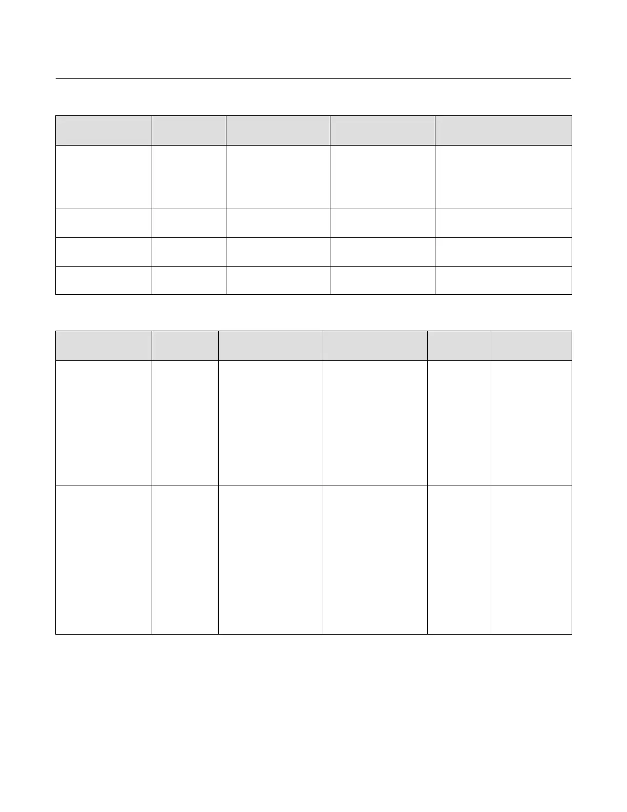
Table C‐2. Setting PlantWeb Alerts (Continued)
PlantWeb Alert
(Group)
(Default Alert Category)
Alert Condition
(Default)
What the Alert is Detecting
Related Parameters
(Default)
Guidelines for Setting
Travel Accumulator
(Travel History)
(Maintenance)
Travel Accumulator
(Disabled)
The accumulated travel has
exceeded the configured limit.
Alert Point (1,000,000)
Deadband (1%)
Packing Bonnets— enable the alert in the
Maintenance Alert Category. When
packing leaks are discovered, set the
Travel Accumulator alert to 90% of the
current Travel Accumulator Value,
triggering an alert prior to anticipated
leak.
Performance Critical
(Performance)
(Failed)
Performance Critical
(Enabled)
Critical performance issues
based on continuous PD tests
internal to the instrument.
None Use default setting
Performance Reduced
(Performance)
(Maintenance)
Performance
Reduced
(Enabled)
Reduced performance issues
based on continuous PD tests
internal to the instrument.
None Use default setting
Performance Information
(Performance)
(Advisory)
Performance
Information
(Enabled)
Performance Information
based on continuous PD tests
internal to the instrument.
None Use default setting
Table C‐3. Using PlantWeb Alerts
PlantWeb Alert
(Group)
(Default Alert Category
Alert Condition
(Default)
What the Alert is Detecting Effect on Valve/Instrument
Recommended
Action
Help
Drive Current
(Electronics)
(Failed)
Drive Current
(Enabled)
The difference between the
expected Drive Current and the
actual Drive Current has
exceeded the Drive Current
Alert Time.
If configured for Self Test
Shutdown, then the transducer
Actual mode is placed Out of
Service until the problem is
fixed. Out of Service results in
the instrument output
pressure(s) and actuator
position being at the Zero
Power Condition.
Check I/P module The instrument has
detected that the
difference between the
expected Drive Current
and the actual Drive
Current is greater than
the configured limit
1) Replace the I/P
module
2) Calibrate the device.
If the problem persists,
replace the printed
wiring board (PWB)
assembly.
Drive Signal
(Electronics)
(Maintenance)
Drive Signal
(Enabled)
If one of the following
conditions exist:
Where Zero Power Condition is
defined as closed:
Drive Signal
< 10% and
Calibrated Travel
> 3%
Drive Signal
> 90% and
Calibrated Travel
< 97%
Where Zero Power Condition is
defined as open:
Drive Signal
< 10% and
Calibrated Travel
< 97%
Drive Signal
> 90% and
Calibrated Travel
> 3%
None - Indicates reduced
performance.
Check instrument
pneumatics
The instrument I/P
drive signal necessary
to generate the
pressure output from
the instrument is not
within the expected
range. Potential causes
include I/P filter
plugged, instrument
pneumatic relay failure,
low supply pressure, air
leaks, or valve sticking.
Test the control valve
assembly for proper
operation. ValveLink
diagnostics can be used
for this purpose.
-Continued-
 Loading...


