Page12of 72
Copyright 2021 FlexRadio. All Rights Reserved. 7 June 2021(FW:0.9.12, Utility: 0.9.12)
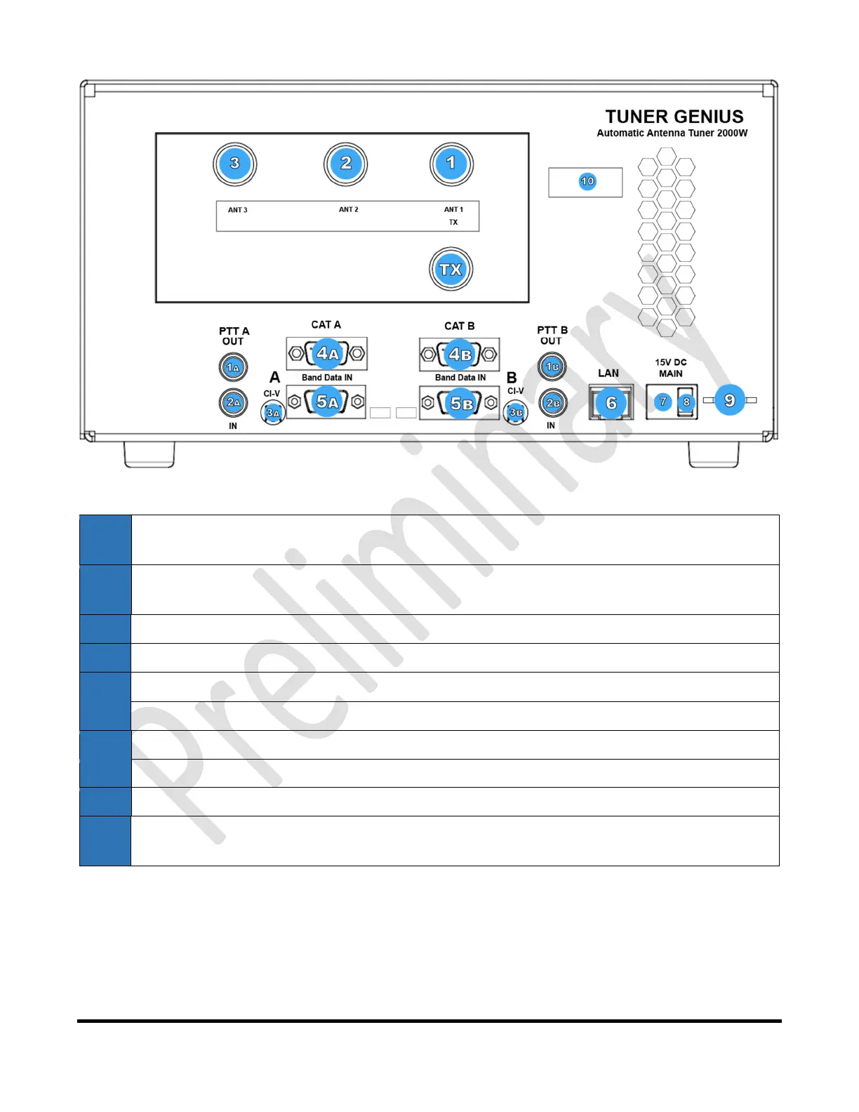
Figure 5-4 1x3 Switching Option Drawing
1a PTTOutput:Opto‐isolatedfemaleRCAconnector.ThecenterpinisgroundedwhensectionA
ofthetuneriskeyedandreadytoacceptRFdrive.
2a PTTInput:Opto‐isolatedfemaleRCAconnector.Groundthecenterpintoshieldtoengage
PTTforthetuner.
3a CI‐VInputA:Opto‐isolated3.5mmfemaleconnectorforIcomradioAbanddata
4a CATInputA:Opto‐isolatedmaleDB9connectorforradioACATcommandinput
5a BCD/PTBInputA:Opto‐isolatedDE‐15femaleconnectorforradioAbanddata
6 Ethernetconnection:RJ45LocalAreaNetworkEthernetconnection
7 DCPowerinput:Nominally15voltsDC,centerpinpositive
8 MainPowerSwitch
9 StationGround
B Binputs:BinputsandoutputareintendedfortheSO2Rswitchingoptionandaredisabledfor
the1x3switchingoption.
5.2.2 SO2R Antenna Switching Option
TheSO2Rback‐paneloptionprovidesspecializedsupportforSO2R(singleoperator,tworadio)radiosport
operations.TheconnectorsarelogicallydividedintothePortAconnectorsandthePortBconnectors.The
tunerwilltunethesignalontheAinputandoutputitontheAoutput,oritwill
tunethesignalontheBinput
andoutputitontheBoutput.TheAand Bsectionsofthe tunercanbecontrolledin dependentlybytworadios.
 Loading...