FLIR CM275 USER MANUAL Document Identifier: CM275-en-US_AA
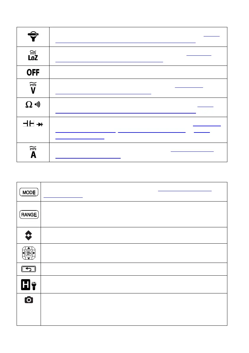
4.2 Function Switch Positions
Select this position when connecting a FLIR Flex Clamp Adaptor. See Section
9.9, Clamp Adaptor (FLEX) Current and Frequency Measurements
Select this position to measure in the low impedance mode. See Section
9.11, Voltage, Lo Z, and Frequency Measurements
Switch the meter OFF (full power saving mode).
Measure AC/DC Voltage through the probe inputs. See Section 9.11,
Voltage, Lo Z, and Frequency Measurements
Measure resistance and continuity through the probe inputs. See Section
9.12, Resistance Measurements and Section 9.13, Continuity Test
Measure capacitance and diode through the probe inputs. See Section 9.16,
Capacitance Measurements, Section 9.14, Classic Diode Test, or Section
9.15, Smart Diode Test
Measure AC/DC current through the clamp jaws. See Section 9.8, Current
and Frequency Measurements
4.3 Function Buttons and Selector/Navigation Pad
Use to select a sub-function of the primary function. See Section 4.3.1, MODE
Button Operation, for details
From Auto range mode, short press to select Manual range mode.
From Manual range mode, short press to change the range (scale). Long press to
return to Auto range mode
Short press to activate/deactivate the Thermal Imager
Use the Navigation pad to enable/navigate menu options
Press to return from a menu screen
Short press to enter/exit the Hold mode. Long press to switch work lights on/off
Short press to save a fully radiometric thermal image or a clamp meter display
screen. Images are saved to the device’s file system accessible in Gallery
mode. The thermal imager must be fully initialized (indicated by display of IR
temperature measurement) before radiometric data can be captured.
 Loading...