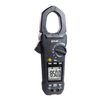
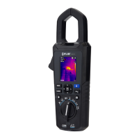
9.11 Voltage, Lo Z, and Frequency Measurements
Warning: If the measured voltage is > 30 V DC or AC RMS, the indicator is displayed.
1. Set the function switch to one of the following positions:
Voltage AC/DC measurements.
Voltage AC/DC measurements with a low impedance circuit, eliminating ghost
voltages. The impedance is approx. 2.5kΩ. The LoZ indicator appears in this mode.
2. Insert the black probe lead into the negative COM terminal and the red probe lead
into the positive terminal. Refer to Fig. 9-4 below.
3. Use the button to select AC or DC measurement.
The indicator appears for AC measurements.
The indicator appears for DC measurements.
4. Connect the probe leads in parallel to the part under test.
5. Read the voltage value on the display.
6. To view the frequency (Hz) of the measured voltage, short press the button
until the Hz reading appears.
7. For VFD mode operation refer to Section 9.4, VFD Mode.
8. For MAX-MIN operation, refer to Section 9.5, MAX-MIN Mode.
Fig. 9-4 Voltage and Frequency Measurements
 Loading...