8.2 Thermal Imager Operation
To customize the Thermal Imager, refer to Section 8.3, Thermal Settings Menu. For
basic operation, follow these steps:
1. Set the function switch to any position.
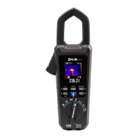
2. Press the IGM button to switch the Thermal Imager ON. Point the thermal
imaging lens (back of meter) toward an area to test.
3. The display will show the temperature in the upper left hand corner for the
targeted area.
4. In the Thermal Imaging mode, use the laser pointer and display cross hairs for
targeting. These can be switched ON or OFF in the Thermal Settings Menu.
5. In the Thermal imaging mode, the meter continues to operate normally as a
Clamp Meter. Note that in the Thermal Imaging mode, view clamp
measurements and function on the left side of the display. If desired, the
meter can be set to image-only mode in the Image Mode menu, see Section
8.4, Image Mode Menu.
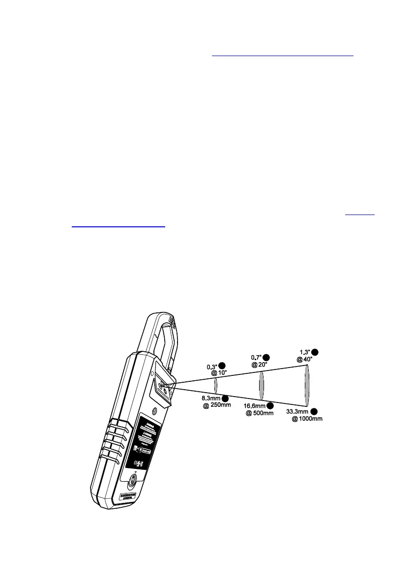
6. The Distance to Spot ratio for the imager is 30:1 meaning that the
measurement spot is 30 times smaller than the distance from meter to spot
(at a distance of 30”, the meter ‘sees’ a target spot of 1”). See Fig. 8-2.
7. The thermal imager’s FOV (Field of View) is 50 degrees (side view) and 38.6
degrees (top view) see Fig. 8-3 (a) and (b).
Fig. 8-2 Distance-to-Spot ratio 30:1
 Loading...