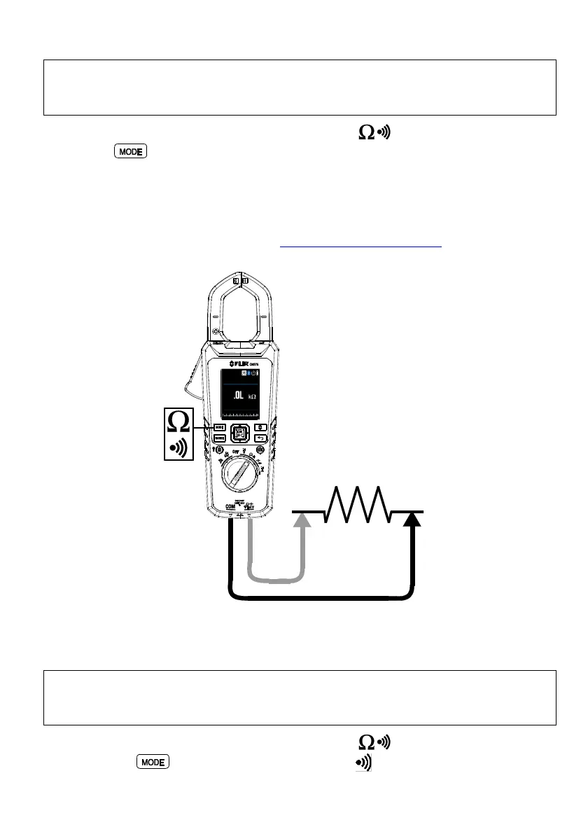
9.12 Resistance Measurements
Warning: Do not perform diode, resistance or continuity tests before removing power
from capacitors and other devices under test during a measurement. Injury to persons
can occur.
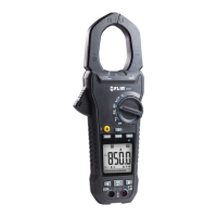
1. Refer to Fig. 9-5. Set the function switch to the position.
2. Use to step to the kΩ display if necessary.
3. Insert the black probe lead into the negative COM terminal and the red probe
lead into the positive Ω terminal.
4. Touch the tips of the probe across the circuit or component under test.
5. Read the resistance value on the display.
6. For MAX-MIN operation, refer to Section 9.5, MAX-MIN Mode.
Fig. 9-5 Resistance and Continuity Measurements
9.13 Continuity Test
Warning: Do not perform diode, resistance or continuity tests before removing the
power from capacitors and other devices under test during a measurement. Injury to
persons can occur.
1. Refer to Fig. 9-5. Set the function switch to the position.
2. Use the button to select continuity. The indicator will appear.
 Loading...