EasyManuals Logo

FLIR CM275 User Manual

FLIR CM275
46 pages
To Next Page IconTo Next Page
To Previous Page IconTo Previous Page
Page #11 background imageLoading...
Page #11 background image
FLIR CM275 USER MANUAL Document Identifier: CM275-en-US_AA
11
4.3.1 MODE Button Sequence of Operations
Rotary Switch Position
Mode Button Sequence of Operations
ACA > Frequency
ACV > DCV > Frequency
Resistance < > Continuity
Capacitance < > Diode
ACA > DCA > Frequency
4.3.2 Navigation Pad/OK Button
There are five (5) buttons arranged in a square that make up the Navigation pad, as
shown in Fig. 4-3.
Fig. 4-3 Navigation Pad
OK button (center): Open the menu and select/change menu options
LEFT/RIGHT buttons: Navigate the menu system
UP/DOWN buttons: Navigate the menu system
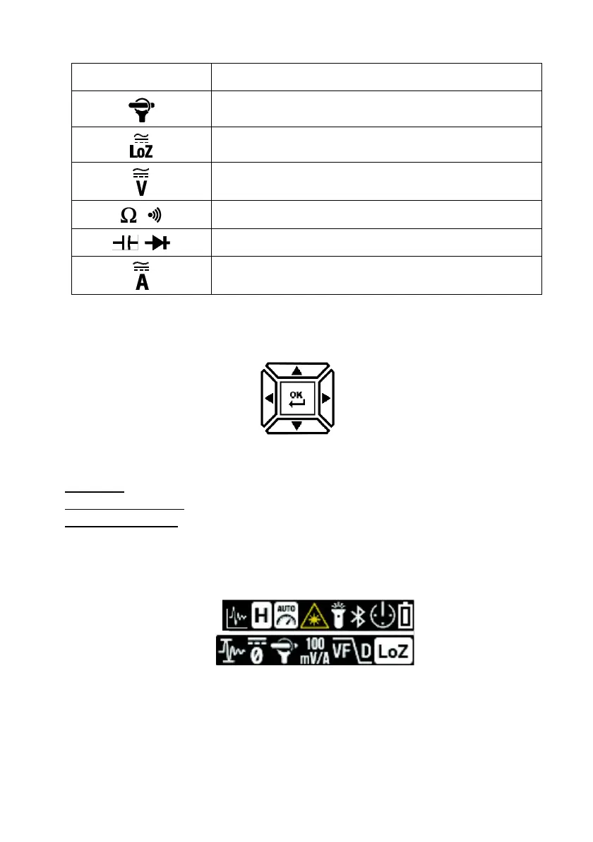
4.4 Status Bar Display Icons
The Status Bar is located at the top right of the display.
Fig. 4-4 Status Bar Display Icons
L to R, row 1: Datalogger, Data Hold, Auto Range, Laser, Work Light, Bluetooth®,
APO, and Battery status
L to R, row 2: Inrush current, DCA Zero, Flex Clamp icon and range, VFD, and Low
Impedance mode
Note that Diode and Continuity symbols also appear in the Status bar area of the display.

Table of Contents

Questions and Answers:

Question and Answer IconNeed help?

Do you have a question about the FLIR CM275 and is the answer not in the manual?

FLIR CM275 Specifications

General IconGeneral
BrandFLIR
ModelCM275
CategoryMeasuring Instruments
LanguageEnglish

Related product manuals