427-0014-00-10 Revision 210 Copyright © 2008 FLIR Systems, Inc. 14
3.3 Input Power
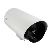
The SR-Series cameras operate on either 24VDC or 24VAC power (nominal). Refer to the
section titled SR-Series Camera Specifications
for additional power requirements. The cameras
provide screw-terminals for receiving tinned leads for input power. For details on how to connect
the leads, refer to the installation section for each specific camera below. The power cable
should be twisted pair or triple, with an overall shield or conduit connected to the enclosure rear
panel ground lug, as described in the previous section.
The system is fuse-protected against over-voltage conditions. A blown fuse is an indication
either that the circuit has been overloaded or that a short circuit has occurred somewhere in the
circuit. A wiring problem may be placing too much of a load on the circuit if a fuse blows after
plugging in or turning on the camera. Before replacing the fuse it is important to identify what
has caused it to fail.
Prior to changing a fuse, turn off the electrical circuit or completely disconnect the camera.
Make certain that no dangerous condition exists before restoring power. Replace the fuse with a
fuse that is of the same rating and proper for the circuit. Never use anything other than a fuse of
proper rating.
3.4 Serial Communications
For serial communications, there are several choices available to the installer and the camera
user. Refer to Table 1: Serial Communication Options in section 2.2 for a list of the protocols
supported by each camera.
If the camera is configured for RS-232 protocol, then the likely choice for camera control and
configuration is a PC or laptop running the appropriate graphical user interface (GUI) software,
which is included with the camera or downloaded from the FLIR website. For the SR-100 and
SR-100P cameras, the software is known as “TVIS-7 User Interface” (refer to section 11.0 SR-
100 & SR-100P Control Using TVIS-7 User Interface for more information). For the other
cameras, the Photon GUI is used.
If the camera is configured for RS-422, then a communication protocol converter (also known as
a serial 232-422 converter) can be used to connect to a laptop or PC running the appropriate
GUI software, allowing a longer cable run. If the SR-100 or SR-100P is configured for RS-422,
then a Pelco D compatible keyboard or other device supporting RS-422 or RS-485 may be
used. The following diagram illustrates these options.
Caution! Failure to disconnect power to the camera while replacing a fuse could result in
accidental injury or death.