427-0014-00-10 Revision 210 Copyright © 2008 FLIR Systems, Inc. 18
2. Route the cable with power/ground and serial leads through the left-hand gland on the
rear enclosure cover (as viewed from the rear of the enclosure).
3. Connect the two power leads according to Table 2: SR-100 Screw Terminals. Connect
the shield of the power cable to the Internal Earth Ground Connection as indicated in the
figure above.
4. Connect the serial communication leads, keeping in mind the protocol for which the
system has been configured (RS-422 standard, RS-232 optional). Connect the shield of
the serial communications cable to the Internal Earth Ground Connection as indicated in
the figure above.
5. Route the video cable through the right-hand gland (when viewing from the rear) on the
rear enclosure cover and crimp the connector to the end of the cable.
6. Connect the cable to the BNC bulkhead connector on the rear of the SR-100.
7. Connect the External Earth Ground lead to the Earth Ground Lug on the inside of the
rear of the enclosure (refer to Figure 3-2: Earth Ground Connection) The Internal Earth
Ground connection should already be connected to the Earth Ground Lug.
8. Make sure that the O-rings supplied on the rear cover of the camera enclosure are
seated properly and free of dirt and debris before reassembly. The O-rings are lubricated
with silicone grease. Replace the rear enclosure cover and tighten the captive screws
appropriately to ensure the system environmental specifications are maintained.
9. Tighten the sealing nut around the cable on each cable gland.
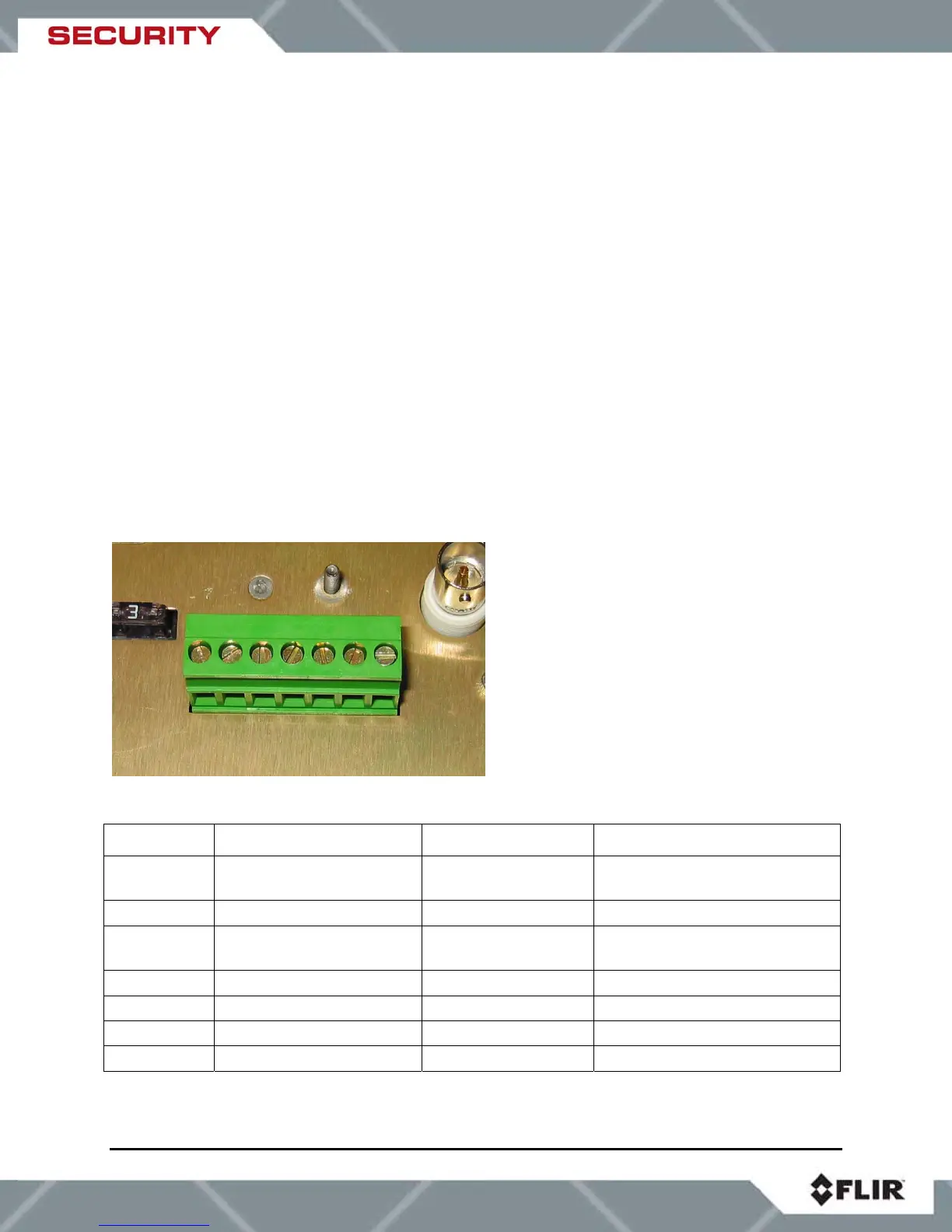
Figure 4-2: Screw Terminal Connector
Pin number Description Direction Comments
1 RS232 Tx or RS422 Tx- Output from camera
PC Data Receive(232),
RS422 TX-, RS422 TX(A)
2 RS422 Tx+ Output from camera
RS422 TX+, RS422 TX(B)
3 RS232 Rx or RS422 Rx+ Input to camera PC Data Transmit(232),
RS422 RX+, RS422 RX(B)
4 RS422 Rx- Input to camera RS422 RX-, RS422 RX(A)
5 Ground N/A GND
6 -Voltage In N/A DC Negative or AC Neutral
7 +Voltage In N/A DC Positive or AC Line
Table 2: SR-100 Screw Terminals
7 6 5 4 3 2 1