427-0014-00-10 Revision 210 Copyright © 2008 FLIR Systems, Inc. 16
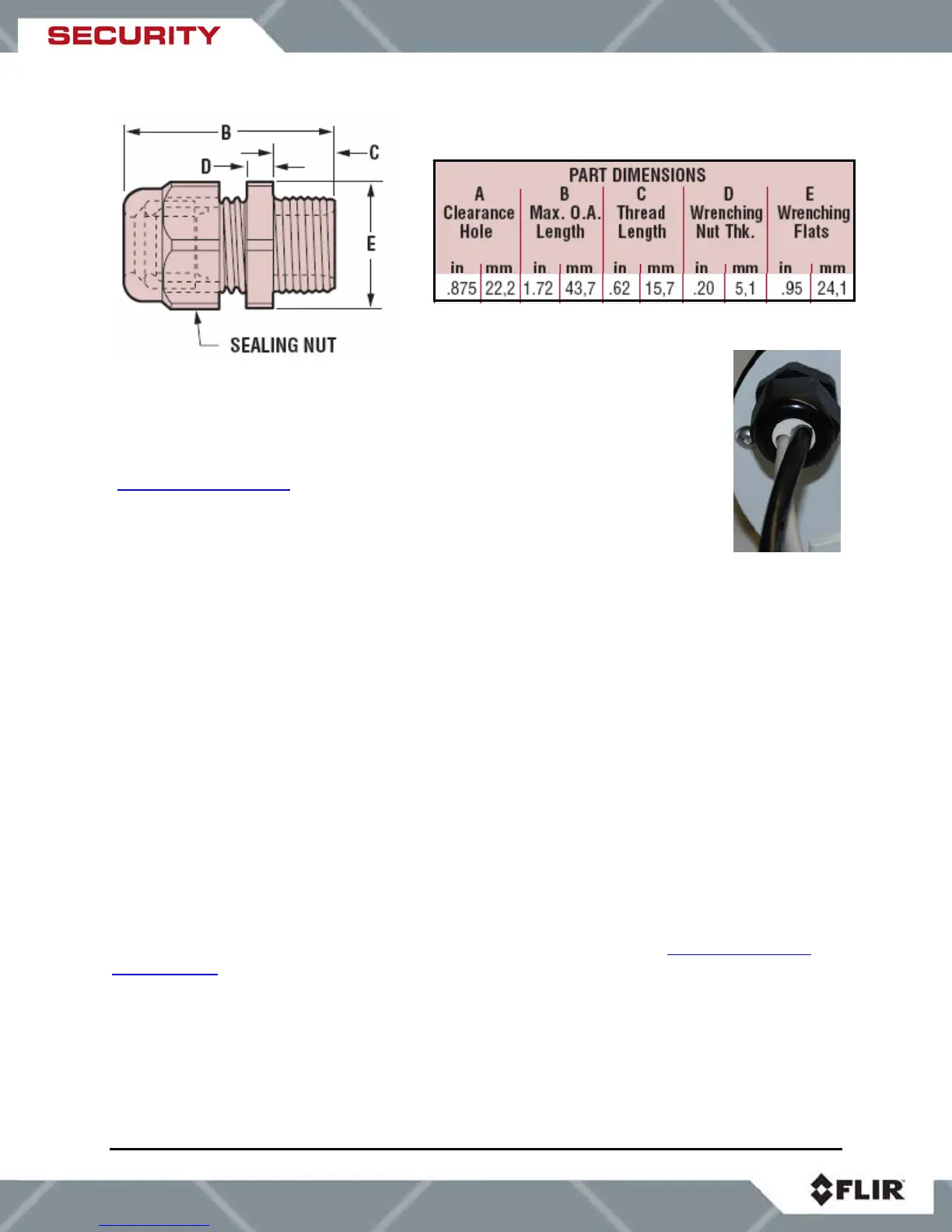
In order to maintain a proper seal, each cable gland should contain a single
cable sheath. Installing more than one cable bundle in the cable seal may
compromise the seal. If separate cables are to be used for power and serial
communications, the gland should be changed to a Heyco
®
-type multi-hole NPT
hub, with the hole size dependent on the cable outside diameter
(http://www.heyco.com/
).
FLIR Systems, Inc. recommends a minimum cable diameter of 1/4” through the
cable glands in order to maintain adequate environmental sealing.
3.6 Analog Video Output
The analog video signal is accessed via a standard coaxial cable BNC connector and meets the
requirements of NTSC or PAL video standards, depending on the configuration ordered. The
analog video signal is intended to drive video coaxial cable (RG-59 or equivalent) and is
designed to transmit a 75 ohm load with minimum signal loss. Excessive signal loss and
reflection occurs if cable rated for other than 75 ohms is used. Cable characteristics are
determined by a number of factors (core material, dielectric material and shield construction,
among others) and must be carefully matched to the specific application. Moreover, the
transmission characteristics of the cable will be influenced by the physical environment through
which the cable is run and the method of installation.
In video security systems, camera signals must travel from the camera to the monitor. Proper
termination of cables is essential to a system's reliable performance. The end point of any video
cable run must be terminated in 75 ohms. Usually, the cable run will end at the monitor, which
will ensure that this requirement is met.
3.7 Camera Mounting
Mounting the SR-Series camera is accomplished using the ¼x20 tripod mount holes on the
underside of the enclosure foot. FLIR Systems recommends using the supplied hardware. The
dimensions of the camera mounting foot are provided in the section titled SR-Series Camera
Specifications for reference. Note, the SR-100P mounting foot dimensions are different than the
other SR-Series cameras.
The enclosure can be mounted via the enclosure foot to a wall mount, ceiling or pedestal mount,
or a pan/tilt mechanism on a wall or ceiling. The enclosure should be attached by a minimum of
two ¼x20 fasteners. For further mounting instructions, see the documentation accompanying
the fixed or pan/tilt mount. The screws that attach the camera enclosure to its foot are 3/32”
head hex screws. The screws that attach the sun shield to the foot are 9/64” hex head screws.