427-0014-00-10 Revision 210 Copyright © 2008 FLIR Systems, Inc. 20
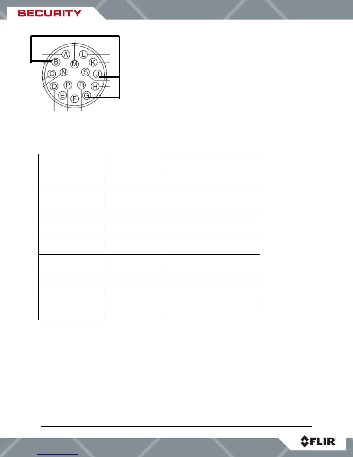
Figure 5-2: Mating connector as seen from end of cable
The following table describes the pin designations for video, power, and communications
signals.
Signal Name Pin Designation Comment
VID OUT A Center (core) of coax video
VID RTN B Coax shield
Not Connected C
Not Connected D
CAM POWER E
CAM POWER RTN F
Shield G Power, Serial communications,
and Video - Tied to pin J
AC LINE H For enclosure heaters
GND J Tied to pin G
RS422 TX- K Camera transmit
RS422 TX+ L Camera transmit
RS422 RX+ M Camera receive
RS422RX- N Camera receive
AC NEUTRAL P For enclosure heaters
Not Connected R
Not Connected S
Table 3: SR-100P Connector pin designations
Pins B, G and J are tied together for proper
ground and shield protection.