427-0014-00-10 Revision 210 Copyright © 2008 FLIR Systems, Inc. 24
Note: the pin numbers are not designated on the connector.
Connector
Pin
Used for Power or Serial
Communications
DB-9 Comments
1 Serial 2 RS-422: Tx-; RS-232: Transmit Data (TD)
2 Serial 7 RS-422: Tx+
3 Serial 3 RS-422: Rx+; RS-232: Receive Data (RD)
4 Serial 8 RS-422: Rx-
5 Serial 5 Signal Ground
6 Power Power DC- or AC neutral
7 Power Power DC+ or AC line
Power Be sure to connect the ground to the lug inside the rear
cover, as shown in Figure 3-2: Earth Ground Connection
Table 4: Power and Serial Pin Designations
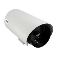
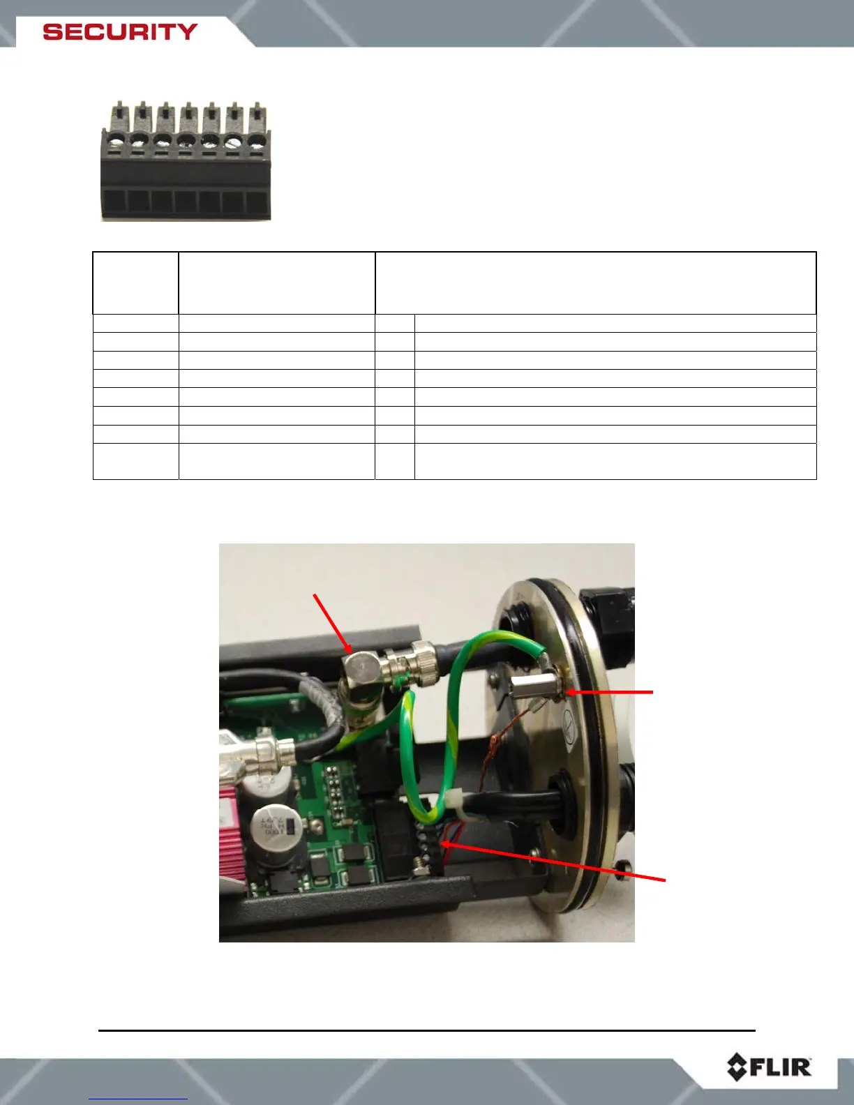
Figure 6-3: SR-Series Connections (VSR-6, SR-19, SR-35, and SR-50)
BNC connector
for video output
Ground lu
Power and
serial
connections