427-0014-00-10 Revision 210 Copyright © 2008 FLIR Systems, Inc. 23
4. Push the camera assembly out of the front of the enclosure from the back using the
lower left and right parts of the chassis as push points. The ground cable inside the
enclosure may have to be temporarily disconnected from the rear plate before removing
the camera.
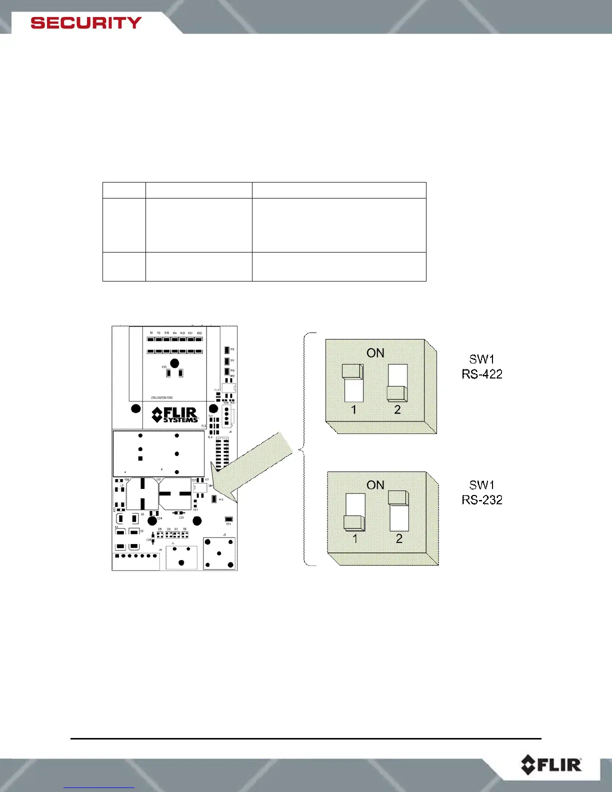
6.2 DIP Switch Settings
The serial protocol (RS-232 or RS-422) is configurable via a switch on the VSR-6, SR-19,
SR35, and SR-50 cameras.
Switch On Off
1 Enables 100 ohm
termination resistor
(set to On for RS-
422)
Removes termination resistor
(set to Off for RS-232
communications)
2 Enables RS-232
communication
Enables RS-422 communication
Note: Daisy-chaining of cameras (point to multi-point configuration) is not supported and the
termination resistor should always be enabled (On) for RS-422 and disabled (Off) for RS-232.
Figure 6-2: Serial Communications DIP Switches
6.3 Camera Installation
Instructions for connecting the power, video and communication leads to the camera are given
below. The power and serial communication leads attach to a detachable connector which is
inserted into a mating connector on the interface board, as shown in Figure 6-3: SR-Series
Connections (VSR-6, SR-19, SR-35, and SR-50). The power and serial communication leads
attach to the detachable connector according to Table 4: Power and Serial Pin Designations.