427-0014-00-10 Revision 210 Copyright © 2008 FLIR Systems, Inc. 15
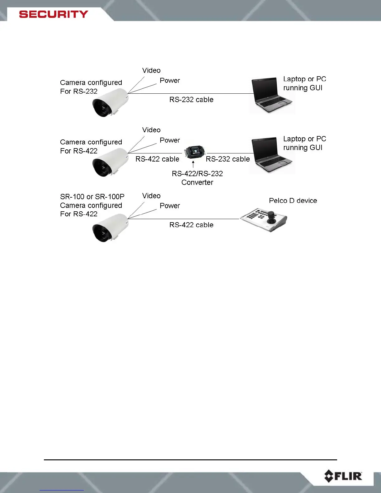
Figure 3-3: Serial Communications Options
The serial cable should be 100 ohm impedance twisted pair with an overall shield. For RS-232,
the cable length should be no longer than 50 feet; for RS-422 the cable should be no longer
than 4000 feet.
3.5 Sealed Cable Glands
With the exception of the SR-100P, cables enter the SR-Series cameras through liquid-tight
compression glands. Be sure to insert the cables through the cable glands on the rear of the
enclosure before terminating and connecting to the camera (the terminated BNC video cable will
not fit through the cable gland). The camera power cable (and serial cable, if used) should be
inserted through the cable gland on the left of the rear of the enclosure, and the video cable
should be inserted through the cable gland on the right. Leave the glands loosened until the
cable installation has been completed.