427-0014-00-10 Revision 210 Copyright © 2008 FLIR Systems, Inc. 17
4.0 SR-100 INSTALLATION
Prior to installing the SR-100, be sure to review the general installation procedures given above.
In particular, be sure to review section 3.2 Ground Connection
. Note the default rate for the SR-
100 camera is 2400 baud.
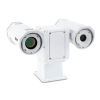
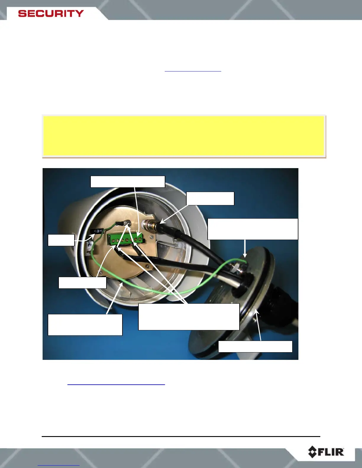
The SR-100 camera provides a removable screw-terminal connector for receiving tinned leads
for input power and serial communication leads. In order to access these interfaces, the rear
panel of the camera must be removed (using the two hex screws). The front panel does not
need to be removed. An example of the SR-100 with rear panel removed is shown in Figure 4-1.
Figure 4-1: SR-100 Connection Terminal
Refer to Table 1: SR-100 Screw Terminals
below for terminal definitions.
1. Loosen or remove the cable gland sealing nuts. Remove the rear enclosure cover using
a 5/64” hex wrench to reveal the green screw-terminal connector. This connector can be
detached from the unit by gently pulling on it. Be careful to maintain the proper
orientation when connecting the leads and reinserting the connector to the camera.
Internal Earth Ground
Connection (supplied)
External Earth Ground
Connection (not shown)
Shields from power and serial
communications (not shown)
are also tied to internal
round
Fuse
Serial Communication
Analog Video
Power In
ut
Rear Enclosure Cove
Caution! Proper ESD protocol should be followed while working inside the unit.
If the green terminal block is removed during installation, be extremely careful to maintain the
proper orientation when connecting the leads and reinserting the connector to the camera.
Caution! Do not connect leads or remove/reinsert the terminal block when power is active.