Page 35CWT S5 Installation & Maintenance ManualIssue 5
Product description
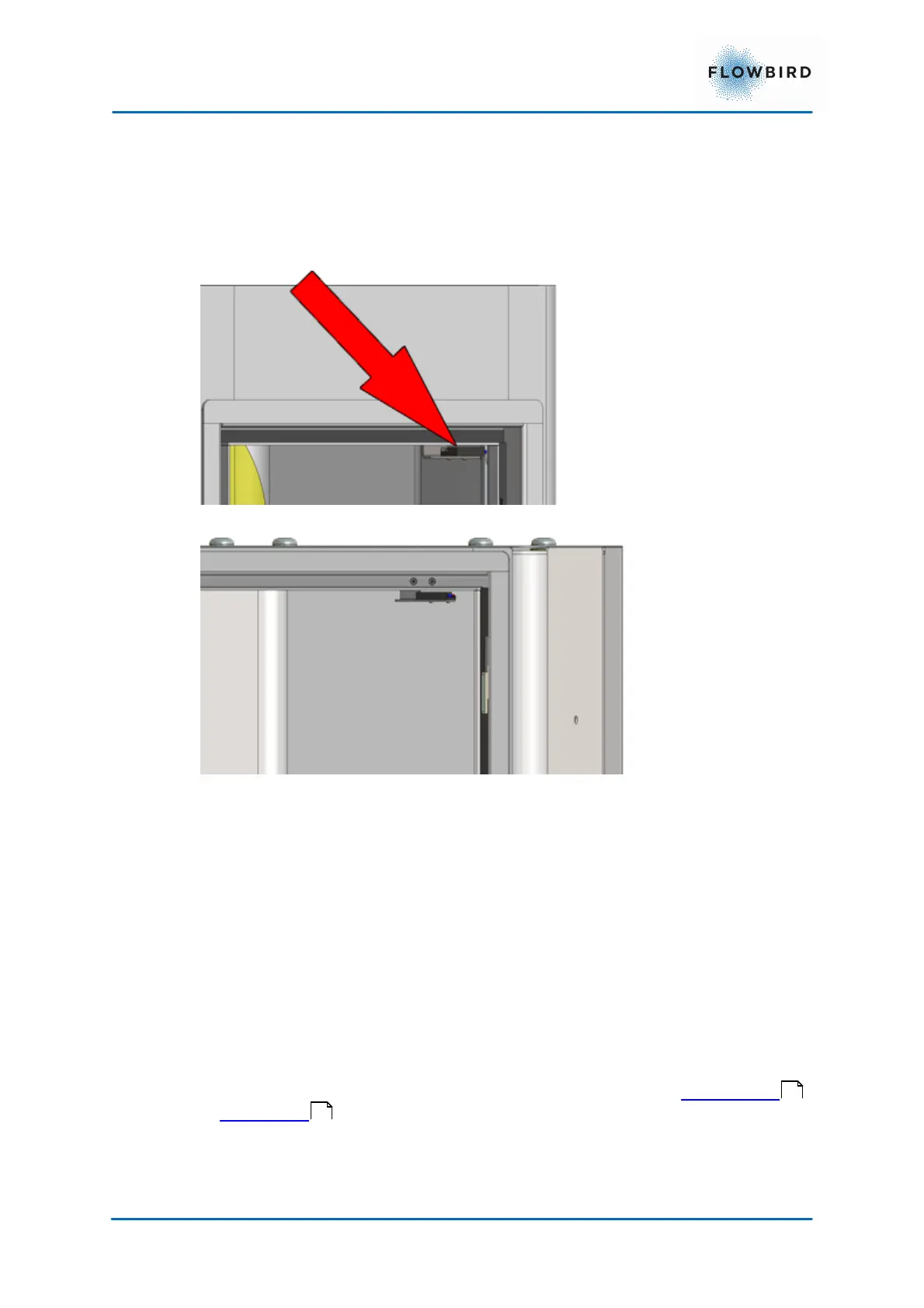
4.7.6.3 Door-open sensors
Both doors have a door-open sensor. All attempts to open the terminal are
logged in the CWT S5 and the information is transferred to WebOffice.
The door-open sensor consists of a permanent magnet mounted on the door
and a magnetic field sensitive sensor mounted inside the door frame.
Figure 30, Door-open sensor in the cabinet.
Figure 31, Door-open sensor in the pedestal.
4.7.7
Heating system
The CWT S5 can be provided with heating in both the cabinet and the pedestal
by means of 100 W heating fans and thermostats adjustable between 0 and 60 °
C.
Both the fan and the thermostat are mounted on existing DIN rails. The heating
fan is connected to one of the two 230 V (115 V UK) outlets (for the heating
radiator) and one 12 V outlet (for the fan itself) in the battery charger module
located in the pedestal.
4.8 Power supply
CWT S5 terminals are powered by a gel type, maintenance free lead-acid battery
placed in the pedestal of the terminal. The battery is charged by mains power
or solar power . In the latter case the terminal has a solar cell panel mounted
at the top.
37
36