Page 73CWT S5 Installation & Maintenance ManualIssue 5
Maintenance
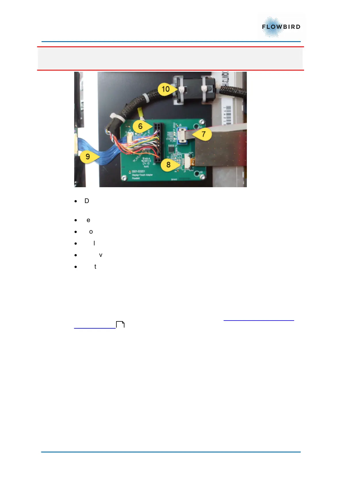
When removing the display unit the cables (8) and (9) will come under tension.
make sure not to damage them.
Figure 61, display module connections
·
Disconnect the display cable (6) and touch controller cable (7).
remove the straps that secure the magnet (10) on the display cable (6).
·
remove the screws marked with red circles
·
loosen the screws in the green circles 7 mm
·
Pull the display unit at the upper corners (red arrows)
·
remove the screws in the green circles
·
Lift the display unit from the ridge marked with the green arrows
We do not recommend opening the display unit as the internal construction is
very sensitive.
Mount the new display unit in reverse order.
Connect the display unit cable to the main board. see Connecting the display to
the CPU board .
74