Multifunction Process Calibrator
Getting Acquainted with the Calibrator
9
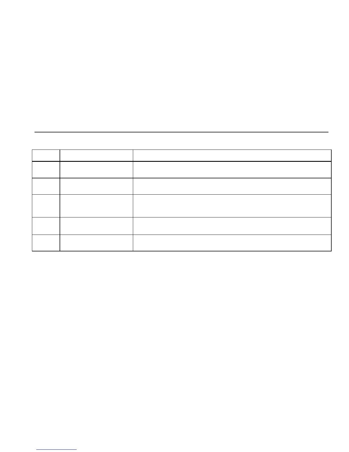
Table 3. Input/Output Terminals and Connectors
No Name Description
A
Pressure module
connector/serial connector
Connects the Calibrator to a pressure module or to a PC for a remote control
serial connection.
B, C
MEASURE V, mA terminals Input terminals for measuring voltage, current, supplying loop power, HART
resistance, switch test options.
D
Thermocouple (TC)
input/output
Terminal for measuring or simulating thermocouples. This terminal accepts a
miniature polarized thermocouple plug with flat, in-line blades spaced 7.9 mm
(0.312 in) center to center.
E, F
SOURCE/ MEASURE V,
RTD, Pulse, Hz, Ω terminals
Terminals for sourcing or measuring voltage, resistance, pulse, frequency, and
RTDs.
G, H
SOURCE/ MEASURE mA
terminals, 3W, 4W
Terminals for sourcing and measuring current and performing 3 W and 4 W RTD
measurements. HART resistor option in mA mode.