96000 Series
Service Manual
4-8
Note
The next steps make the low frequency flatness adjustment of the 50
Ω
Leveling Head using the AC Measurement Standard.
7. Using the blue arrow keys and rotary knob, edit the UUT Actual output until
the AC Measurement Standard indicates the Target value stated. Push
Accept Target.
Note
If the AC Measurement Standard used does not read the UUT
output in dBm directly, calculate the desired value using the
following formula:
()
=Ω
−3
2
10
50
log1050
V
dBm
Alternatively, the UUT units selection can be changed to V rms to
display targets and adjust output values directly in rms voltage. Push
and select the required units.
Note
Measurements made on the 5790A 2.2 mV range (at levels below
40 dBm) require correction for the 2.2 mV range linearity error.
8. Push Next Target.
9. Repeat steps 7 and 8 for all points requiring the use of the AC Measurement
Standard (the UUT text box will indicate Use Precision AC Voltmeter). Set the
UUT to STBY.
10. Disconnect the AC Measurement Standard and feedthrough termination
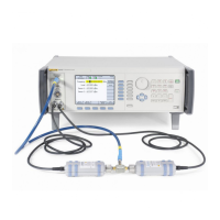
from the Leveling Head. Connect the UUT 50 Ω Leveling Head to the input
of the 50 Ω Thermal sensor using a Type-N female-to-female adapter. See
Figure 3-6 for equipment connections.
Note
The insertion loss of the 50
Ω
Type-N female-to-female adapter
must be taken into account at each adjustment frequency.
11. Set the Power Meter for 0.001 dB resolution.
12. Set the UUT to OPER.
Note
The next steps make the high-level flatness adjustment of the 50
Ω
Leveling Head using a Power Meter and sensor.
13. Enter the measurement frequency corresponding to each Target into the
Power Meter to enable cal factor (frequency) correction.

 Loading...