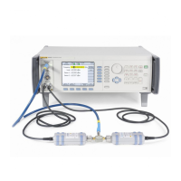
96000 Series
Service Manual
3-36
Table 3-16. 50 Ω Leveling Head VSWR Test (96040A and 96270A)
Level Frequency
Signal Generator
Frequency
Maximum VSWR
+13 dBm
100 MHz 100.000 01 MHz <1.05
2 GHz 2.000 000 01 GHz <1.10
3 GHz 3.000 000 01 GHz <1.15
4 GHz 4.000 000 01 GHz <1.20
+3 dBm
100 MHz 100.000 01 MHz <1.05
2 GHz 2.000 000 01 GHz <1.10
3 GHz 3.000 000 01 GHz <1.15
4 GHz 4.000 000 01 GHz <1.20
-7 dBm
100 MHz 100.000 01 MHz <1.05
2 GHz 2.000 000 01 GHz <1.10
3 GHz 3.000 000 01 GHz <1.15
4 GHz 4.000 000 01 GHz <1.20
Level Accuracy – 75
Ω
Levelling Head (96040A and 96270A)
Equipment required for this test:
• AC Measurement Standard
• Precision 75 Ω feedthrough termination
• 75 Ω Type-N female-to-BNC male adapter
• Power Meter
• Power Sensor, 75 Ω
• Precision Adapter, Type-N female-to-female, 75 Ω
• 75 Ω to 50 Ω impedance-matching pad
• Spectrum Analyzer
• 75 Ω Leveling Head (supplied with UUT)
Use the subsequent procedure to verify the absolute level accuracy of the UUT
75 output. The procedure makes use of an AC Measurement Standard,
followed by a Power Meter and sensors, and finally, a Spectrum
Analyzer/Measuring Receiver. At various points within the process values
previously measured using one reference device are required for subsequent use
with another device. To aid readability, the procedure is divided into stages,
however the complete procedure must be done in the sequence described. Fluke
Calibration recommends that the users familiarize themselves with the entire
absolute level accuracy verification procedure before commencing.
Note
Unwanted interference from signals at 10 MHz due to the frequency
reference outputs of equipment operating in the vicinity of the test
setup or the equipment used during the tests can cause erroneous
results. To avoid such problems, when test frequencies are from
10 MHz to 300 MHz, add a small offset (50 kHz) to the nominal
frequency if the test frequency is a multiple of 10 MHz.

 Loading...