96000 Series
Service Manual
4-14
Microwave Output Adjustment – With Low-Level Output Option Fitted
Equipment required:
• AC Measurement Standard
• Precision feedthrough termination, 50 Ω
• 50 Ω Type-N female-to-BNC male adapter
• Power Meter
• Power Sensor, Thermal, DC - 27GHz, 50 Ω
Note
If another Adjustment procedure was just completed, omit steps 1
and 2, below.
1. On the UUT, push , followed by the softkeys Support
Functions>Calibration>Adjust Instrument.
2. Using the keypad, enter the password, and push .
3. Push the softkey Adjust Microwave.
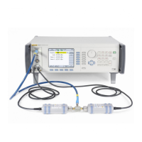
4. Connect the UUT Microwave Output to the input of the AC Measurement
Standard via a precision 50 Ω feedthrough termination.
Note
For measurements made with the AC Measurement Standard during
calibration adjustment, use a common mode choke as described in
the Level Accuracy Test. Connect the choke input low to the AC
Measurement Standard chassis ground. Keep the ground
connection as short as possible and set the AC Measurement
Standard to Internal Guard.
5. Set the UUT to OPER.
Note
The next steps make the low frequency flatness adjustment of the
Microwave Output using the AC Measurement Standard.
6. Using the blue arrow keys and rotary knob, edit the UUT Actual output until
the AC Measurement Standard indicates the Target value stated. Push
Accept Target.
Note
If the AC Measurement Standard used does not read the UUT
output in dBm directly, calculate the value using this formula:
()
=Ω
−3
2
10
50
log1050
V
dBm
Alternatively, the UUT units selection can be changed to V rms to
display targets and adjust output values directly in rms voltage. Push
and select the required units.
Note
Measurements made on the 5790A 2.2 mV range (at levels below
40 dBm) require correction for the 2.2 mV range linearity error.

 Loading...