96000 Series
Service Manual
3-20
2. Set the UUT as follows:
Note
For the 96270A, ensure the Leveling Head output is selected.
Mode Leveled Sine
Frequency 1 kHz
Level +16 dBm
Output OPER
3. Allow the AC Measurement Standard to make several measurements and the
reading to settle. Convert the settled reading from V rms to dBm using this
formula:
dBm (50 )
×
=
001.050
10
2
10
V
Log
The result must be within the tolerance listed in Table 3-10.
4. Set the UUT output to the next frequency listed in Table 3-10 for this test
amplitude.
5. Repeat step 3 and confirm that the measured output level is within the
tolerance shown in Table 3-10.
6. When the test frequency is 100 kHz, record the measured level in dBm as P
1
for use later in this procedure.
7. Repeat steps 2 through 7 for the next test amplitude listed in Table 3-10,
applying the 5790A 2.2 mV range linearity error correction at levels below
-40 dBm .
High Frequency Test Points (steps 8-27)
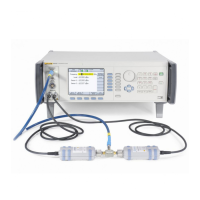
8. Connect the 50 Ω Leveling Head to the 50 Ω thermal Power Sensor via a
precision 50 Ω Type-N female-to-female adapter. See Figure 3-6 for
equipment connections.
9. Set the UUT as follows:
Mode Leveled Sine
Frequency 100 kHz
Level +16 dBm
Output OPER

 Loading...