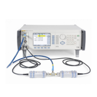
96000 Series
Service Manual
3-32
Note
The 6 dB attenuator is used to minimize mismatch errors. In some
cases, additional attenuation is required to satisfy alternative
Measuring Receiver maximum input limitations.
Note
Unwanted interference from signals at 10 MHz due to the frequency
reference outputs of equipment operating in the vicinity of the test
setup or the equipment used during the tests can cause erroneous
results. To avoid such problems, add a small offset (50 kHz) to the
listed nominal test frequency.
2. On the UUT enable the REF FREQUENCY OUTPUT at 10 MHz, set the UUT
as follows:
Note
For the 96270A, ensure the Leveling Head output is selected.
Frequency 10 MHz
Level +10 dBm
Output OPER
3. Let the Measuring Receiver tune the input signal, and then set the controls to
measure RF level, relative (dB) to the current input level.
4. At each attenuation level listed in Table 3-15, allow the Measuring Receiver
reading to stabilize, ensuring the indicated value is within the relevant
tolerance.
5. Return the UUT attenuation to 0 dB (+10 dBm).
6. Repeat steps 2 through 6 at the attenuation levels shown in Table 3-15 for
frequencies of 50 MHz and 100 MHz.
7. Set the UUT to STBY.
Table 3-15. 50 Ω Leveling Head Attenuation Accuracy (50 Ω) Test Points
Nominal Attenuation
Absolute Output Level
Specification
0 dB +10 dBm Reference
-7 dB +3 dBm ±0.02 dB
-17 dB -17 dBm ±0.02 dB
-27 dB -27 dBm ±0.02 dB
-37 dB -37 dBm ±0.02 dB
-47 dB -47 dBm ±0.02 dB
-57 dB -57 dBm ±0.03 dB
-67 dB -67 dBm ±0.05 dB
-76 dB -66 dBm ±0.07 dB
-85 dB -75 dBm ±0.07 dB
-95 dB -85 dBm ±0.15 dB
-105 dB -95 dBm ±0.15 dB

 Loading...