Integrated Network Analyzer
Using the Analyzer
31
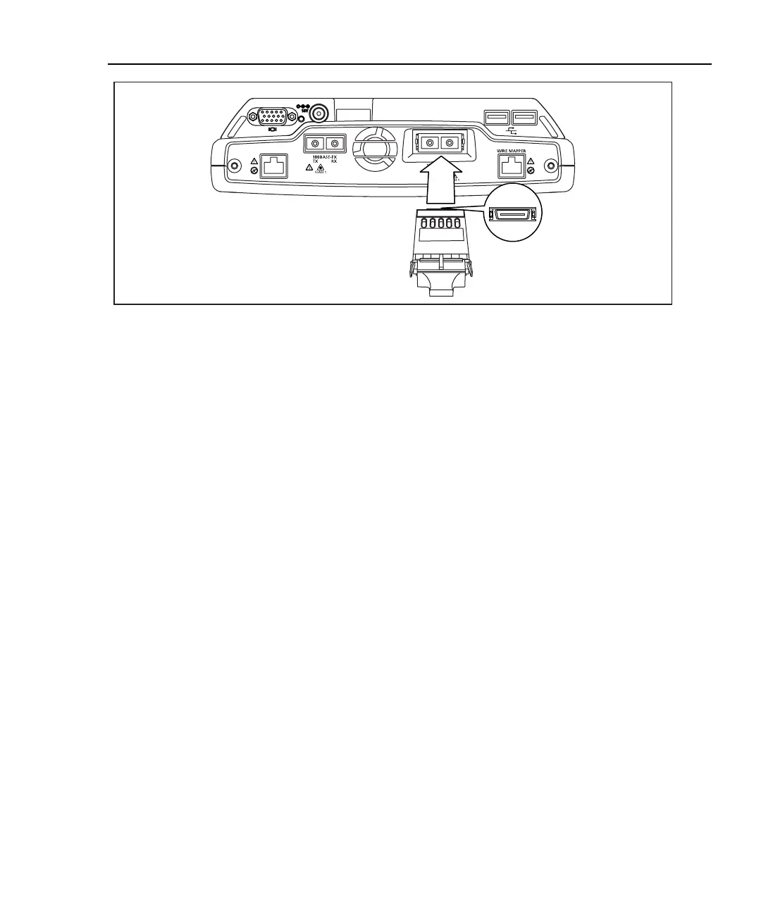
10BASE-T
100BASE-TX
Top
aww14f.eps
Figure 17. Installing a GBIC Module
Note
Though most GBICs are designed to be hot-swappable, i.e. changed
with the analyzer power on, it is recommended that the analyzer be
powered off or placed in suspend mode prior to changing the GBIC.
This will reduce the possibility of damage to the GBIC.
WWarning
GBIC modules are Class 1 laser light emitting products.
Never look into the GBIC module while it is on, otherwise
damage to the eyes, including blindness, can occur.
Windows Network Configuration
The Windows network configuration is preconfigured for communication with the
OptiView
TM
analyzer data acquisition board. The Ethernet and fiber connectors are
part of the data acquisition board. DO NOT modify the Windows IP address
settings for the data acquisition board. You may add additional interfaces that have
their own TCP/IP protocol settings. You may need to modify other network
configurations such as WINS (the DNS servers should be 192.168.111.112).
 Loading...