–
When installing the HF input, make sure that the connector
pins fit exactly in the holes in the connector housing (C).
PM9626 (GPIB Interface)
–
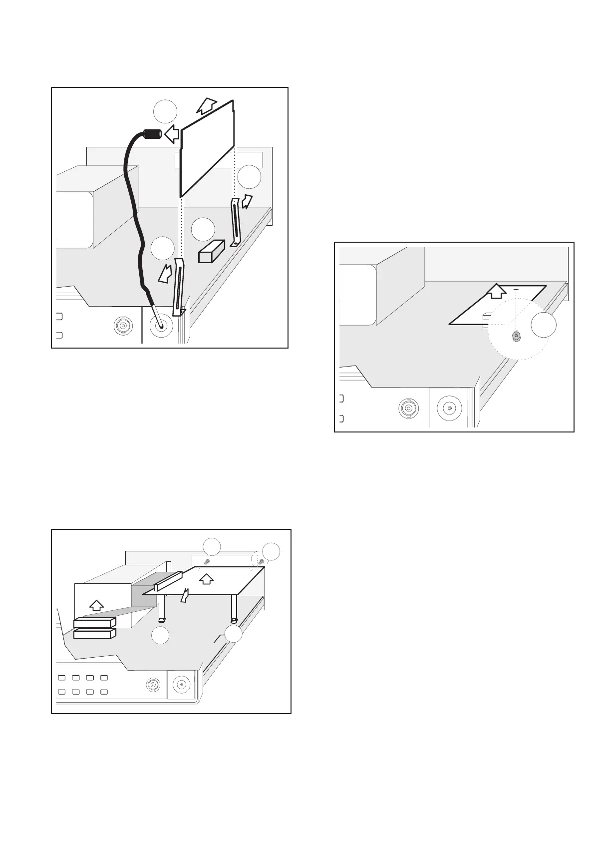
Disconnect the power cable.
–
Remove the cover from the counter.
–
Loosen the two screws (A) holding the GPIB interface to the
rear panel.
–
Disconnect the interface cable from P103.
–
Move the GPIB interface pca toward the front of the counter
and lift the pca supports out from the “keyholes” (B) on the
main PCA.
PM9691 or PM9692 (Oven
Oscillator)
–
Disconnect the power cable.
–
Remove the cover of the counter.
–
Remove the two screws (A) holding the oscillator to the main
pca from underneath.
–
Press the clip (B) gently to the front of the counter and lift the
oscillator straight up.
–
Make sure that jumpers J14 and J15 are set in the correct posi
-
tion.
–
When fitting the oscillator, make sure that the connector pins
fit exactly in the holes in the connector housing.
Disassembly, PM9626 (GPIB Interface) 3-3
B
A
B
A
Fig. 3-4 Loosen the two screws in the rear panel and dis
-
engage the board from the keyholes.
A
Fig. 3-5 One of the two screws holding the oven oscillator
in place.
A
B
B
C
Fig. 3-6 Removing the HF Input.