General Information
WARNING: Before turning on the instrument, ensure
that it has been installed in accordance with the In
-
stallation Instructions outlined in Chapter 3 of the
Operators Manual.
This performance procedure is intended to:
–
Check the instrument’s specification.
–
Be used for incoming inspection to determine the acceptability
of newly purchased instruments and recently recalibrated in
-
struments.
–
Check the necessity of recalibration after the specified
recalibration intervals.
NOTE: The procedure does not check every facet of the in
-
strument’s calibration; rather, it is concerned primarily
with those parts of the instrument which are essential
for determining the function of the instrument.
It is not necessary to remove the cover of the instrument to perform
this procedure.
If the test is started less than 20 minutes after turning on the instru
-
ment, results may be out of specification, due to insufficient
warm-up time.
Recommended Test
Equipment
*) Two of the cables must have 10 ns difference in delay, for ex
-
ample: 5 ns and 15 ns.
Preparations
Power up your instruments at least 20 minutes be
-
fore beginning the tests to let them reach normal
operating temperature. Failure to do so may result
in certain test steps not meeting equipment specifi
-
cations.
Front Panel Controls
Power-On Test
At power-on the counter performs an automatic self-test of the fol
-
lowing:
–
Microprocessor
–
RAM
–
ROM
–
Measuring circuits
–
Display
If a GPIB interface is installed, the GPIB address is displayed.
If there are any test failures, an error message is shown.
–
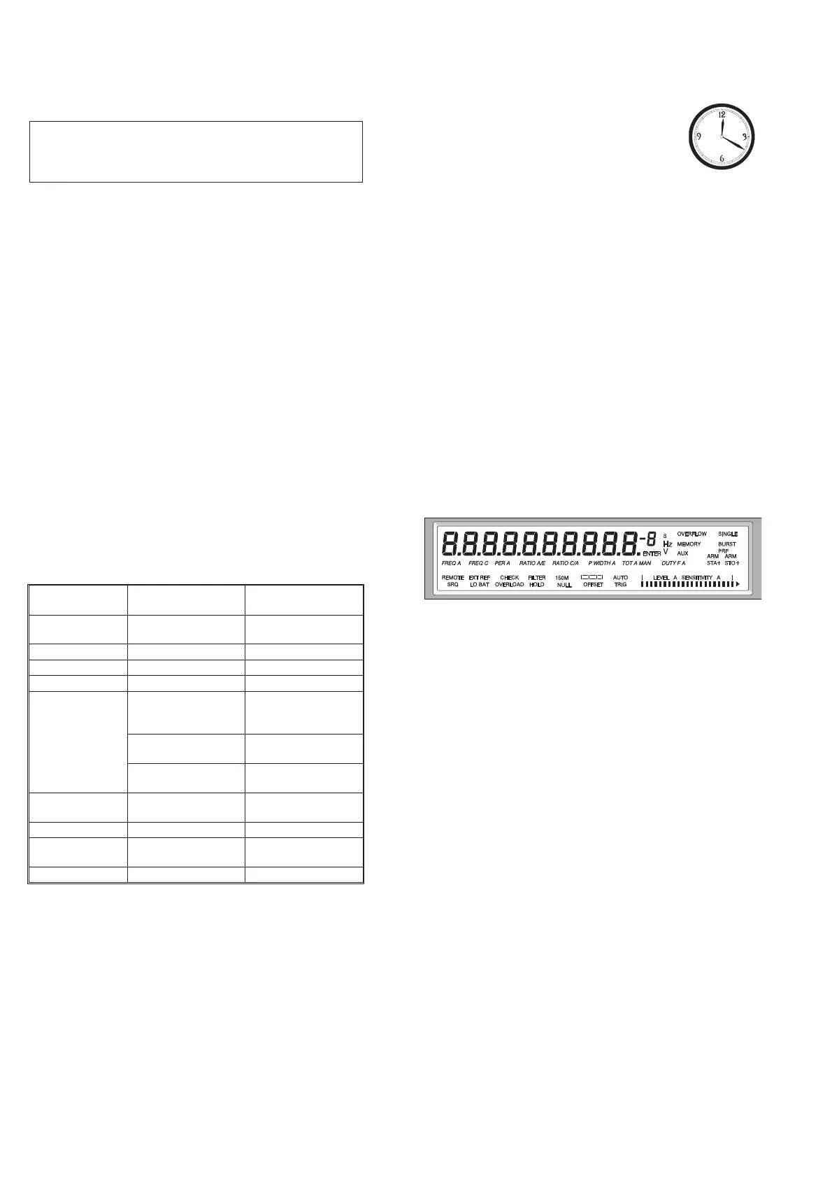
Turn on the counter and check that all segments light up on the
display and that no error message appears.
Internal Self-Tests
The different built-in test routines invoked by the power-on test can
also be activated from the front panel as follows:
–
Enter the Auxiliary Menu by pressing AUX MENU.
–
Select the test submenu by pressing DATA ENTRY up or
down.
–
Enter the test menu by pressing the ENTER key.
Selections for internal self-tests are:
1 TEST ALL (Test 2 to 5 in sequence)
2 TEST RO (ROM)
3 TEST RA (RAM)
4 TEST LOGIC (Measuring Logic)
5 TEST DISP (Display Test)
–
Use DATA ENTRY up/down to select TEST ALL, then press
ENTER.
–
If any fault is detected, an error message appears on the dis
-
play and the program halts.
–
If no faults are detected, the program returns to measuring
mode.
2-2 Performance Check, General Information
Type of instru
-
ment
Required
Specifications
Suggested
Equipment
LF Synthesizer Square;
Sine up to 10 MHz
Power Splitter 50 W PM9584/02
T-piece
Termination 50 W PM9585
Reference oscilla
-
tor
10 MHz ±0.1 Hz for
standard oscillator
Fluke counter with
calibrated option
PM9691
10 MHz ±0.01 Hz for
PM9691 & PM9692
Fluke PM6685R or
PM6681R
10 MHz ±0.0001 Hz
for PM6685R
Fluke 910R or Ce
-
sium Standard
HF signal genera
-
tor
0.5 GHz (no presc.)
3.3 GHz (option 10)
Pulse Generator 125 MHz
Oscilloscope with
probes
350 MHz
BNC cables 5 to 7 cables *
Table 2-1 Recommended Test Equipment.
Fig. 2-1 Text on the display.