Repair
Troubleshooting
n
Required Test Equipment
To be able to test the instrument properly using this manual you will
need the equipment listed in Table 9-1. The list contains specifica
-
tions for the critical parameters.
n
Operating Conditions
Power voltage must be in the range of 90 to 260 VAC.
WARNING: Live parts and accessible terminals which
can be dangerous to life are always exposed inside
the unit when it is connected to the line power. Use
extreme caution when handling, testing or adjusting
the counter.
n
Primary circuits
CAUTION: If you adjust the +5 V trimmer you have to
adjust the complete instrument.
To verify the power supply proceed as follows:
–
If the primary fuse is broken, there is a short circuit in the pri
-
mary circuits. Use a DMM and try to locate the fault by resis
-
tance measurements.
–
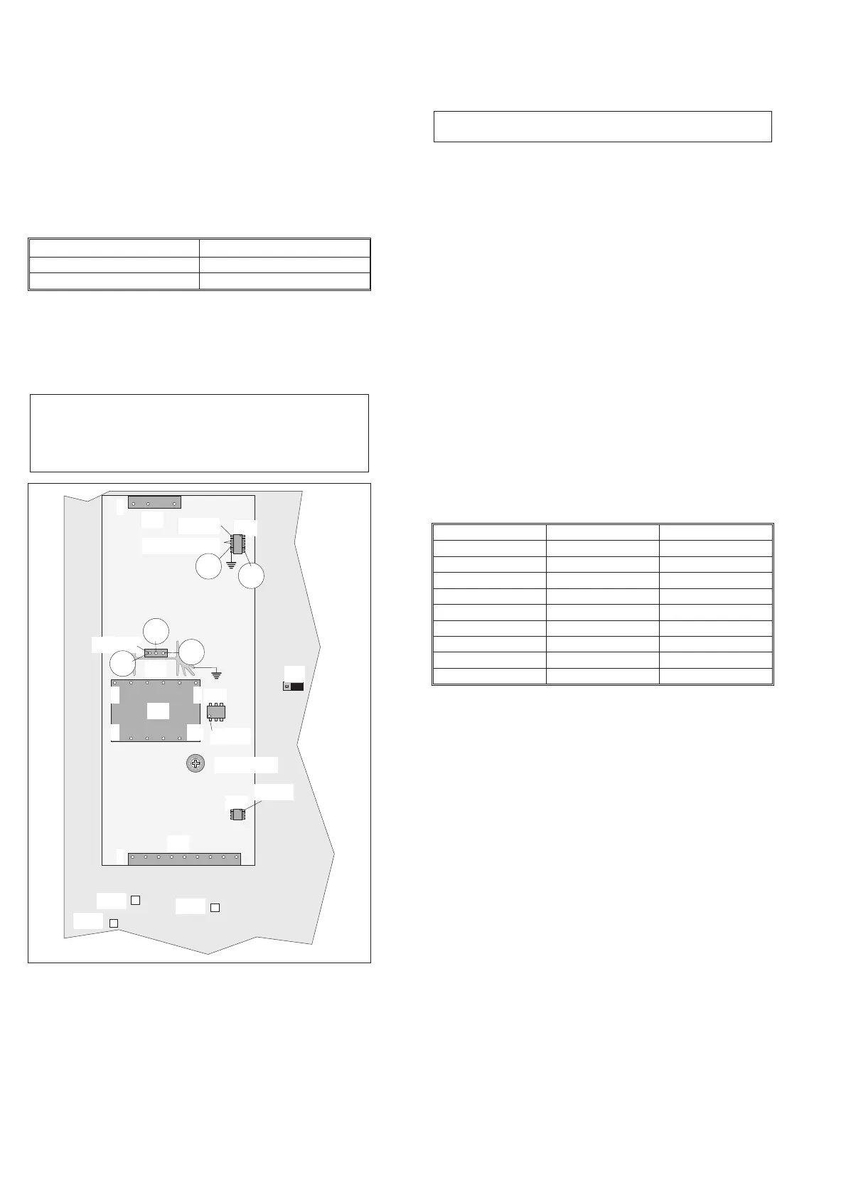
Remove the cover from the power supply.
–
Disconnect the power module from the main PCA and check
the resistance between pin 1 and 4 on the transformer T01, see
Fig. 9-9. If the DMM shows a short circuit, the fault is
proabably a broken transistor V01. Put the power module back.
–
Connect the counter to the line power via an insulating trans
-
former with separate windings.
–
Set the counter to STAND-BY mode.
–
Check that the voltage between J9 and J10 is in the range of
90 to 260 V
AC
.
–
Check that the DC voltage between pin 1 and 4 on T01 is
about Ö2 times the input AC voltage. If not, use traditional
faultfinding techniques to locate the fault.
–
Disconnect the secondary load by moving the jumper J16 to its
alternative position.
–
Check the “STAND BY” voltages according to Table 9-2.
–
Restore the jumper J16 to its normal position.
–
Check the waveforms in Fig. 9-10 at the corresponding
testpoints in Fig. 9-9 to verify the primary circuits. Use the
heat-sink of V01 as ground.
NOTE: U01 and U03 are located at the bottom side of the
PCA.
n
Secondary circuits
For secondary circuits see Chapter 5, Repair, Power Supply.
Safety Inspection and Test After Repair
n
General Directives
After repair in the primary circuits, make sure that you have not re
-
duced the creepage distances and clearances.
Before soldering, component pins must be bent on the solder side of
the board. Replace insulating guards and plates.
9-6 Repair
Type Performance
DMM 3.5 digits
Oscilloscope 50 MHz 2-channel
Table 9-1 Required test equipment.
Test points Ground Voltage
U03 pin 11 & 12 U03 pin 8 +10 to +13.5 V
U03 pin 14 U03 pin 8 +5.0 V
V01 source U03 pin 8 +10 mV
U02 pin 1 Amplifier Screen +8.2 V
U01 pin 1 Amplifier Screen +4.4 V
TP15 Amplifier Screen +5.1 V
TP16 Amplifier Screen +14.8 V to +21 V
TP17 Amplifier Screen –12.5 V to –7.5 V
TP21 Amplifier Screen +12 V ±0.5 V
Table 9-2 Stand-by voltages.
TP15
T01
16
127
+5V adjust
V0 1
U02
U01
»+4.4V
U03
+10 to 13.5V
J16
C
D
E
»+8.2V
»+5.0V
»+10mV
A
B
TP16
TP17
1
1
P0 2
P0 1
Fig. 9-9 Test points and voltages for the power supply.