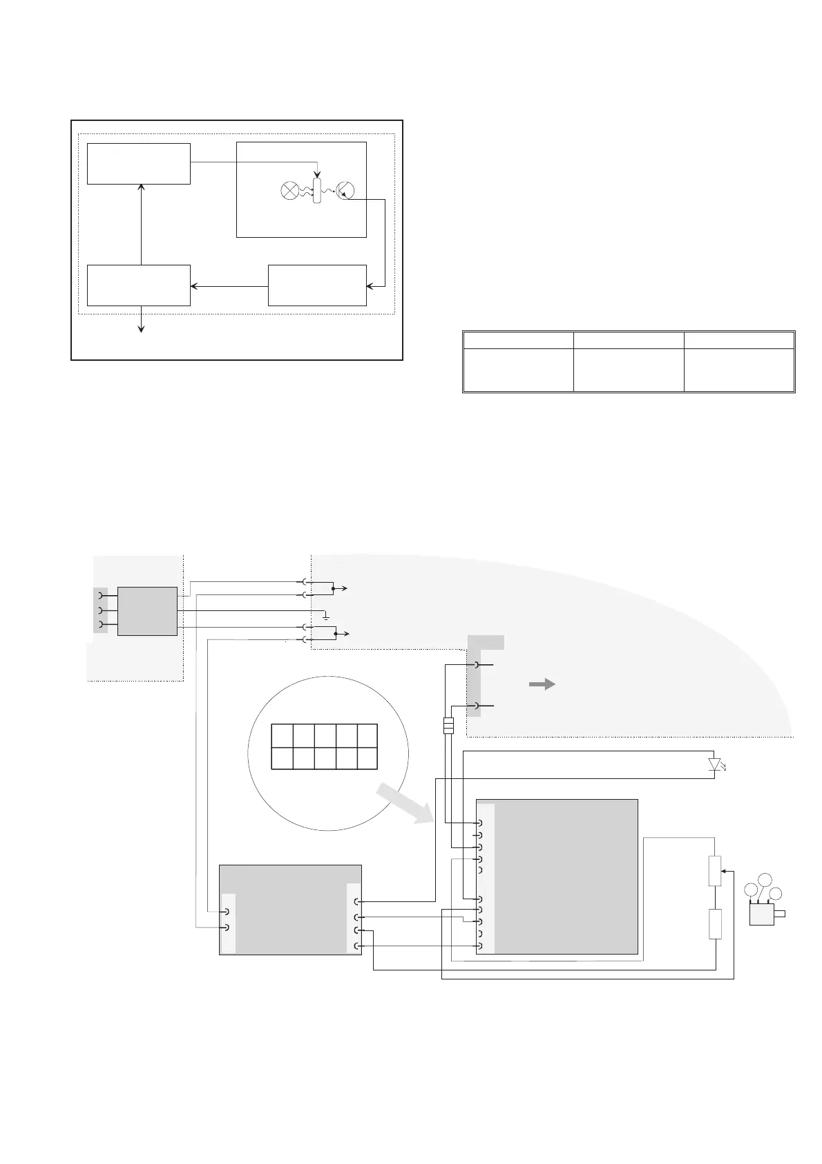
quency is locked to the atomic-standard “resonance frequency” of
the rubidium atom, see Fig. 9-14.
A microwave signal that is derived from the VCXO tunable oscillator
is applied to rubidium vapor contained within a heated glass cell.
Light from a rubidium lamp is passed through the cell and
illluminates a photo detector causing current to flow in the detector.
As the applied microwave signal approaches the frequency that cor
-
responds to the ultra stable rubidium atomic resonance frequency, the
rubidium light entering the glass cell is absorbed by the rubidium va
-
por to an increased extent causing a decrease in the photo detector
current. This “darkening” effect is used to generate an error signal
which permits continuous regulation of the quartz crystal oscillator
output frequency, thereby locking it to the frequency of the atomic
standard .
Calibration Adjustments
NOTE: Before Calibration Adjustment, the Rubidium time
base must have been in operation for more than 24
hours.
Required Test Equipment
Setup
–
Connect the counter to the line power.
–
Press PRESET, then ENTER.
–
Press AUX.
Calibration Adjustments 9-13
Type Performance Model
10 MHz reference £1x10
-10
Calibrated Rubidium
oscillator or Cesium
atomic standard
Table 9-5 Required test equipment.
A2
RUBIDIUM
OSCIL LATOR
TYPE LPRO
D1 UNLOCKED
UNIT 1J9
J10
SAFETY EARTH
5
3
2
1
3
1
2
0to
60v
CNT-85R REAR
PA NEL
LINE
FILTER
FREQ.
ADJUS T
REAR VIEW
OF P3
3
J24
R1
1k
P3
1
2
3
4
5
6
7
8
9
10
A1AUX POWER
SUPPLY
5
4
+24V
0V
P2
3
1
N
L
P1
1
2
9
10
0V
3
2
+24V
L1-L3
J3
J4
R2
3.83k
10 MHz
Fig. 9-13 Wiring diagram showing the interconnections between the Rubidium timebase, its power supply, and the main PCA.
PM6685R REAR
PANEL
Frequency multiplier/
Sy nthesizer
20 MHz Voltage tun able
Quartz Oscillator
(VCXO)
Feedback
electron ics
(Servo)
DC-error
sign a l
DC cor rection
voltage
6.8 GHz
10 MHz output
Rub idium
lamp
R ub idium
cell
Detector
Fig. 9-14 Block diagram showing the principle of a Rubidium
Atomic Standard.