Introduction
Required Test Equipment
* For adjustment of PM9691 and PM9692 Oven Oscillators only.
Note: Only calibrated instruments should be used.
Preparation
WARNING: Live parts and accessible terminals which
can be dangerous to life are always exposed inside
the unit when it is connected to line power. Use ex
-
treme caution when handling, testing, or adjusting
the counter.
Before beginning the calibration adjustments, power up the instru
-
ment and leave it on for at least 30 minutes to let it reach normal oper
-
ating temperature.
Power Supply
CAUTION: If you adjust the +5 V trimmer you have to
adjust the complete instrument.
n
Setup
–
Remove the protective cover above the power module.
WARNING: The heat sink inside the power module is
connected to line power.
–
Connect the counter to line power.
–
Switch on the counter.
–
Press PRESET, then press ENTER.
NOTE: The backlight must be switched on during the adjust
-
ment of the power module.
n
Adjustment
–
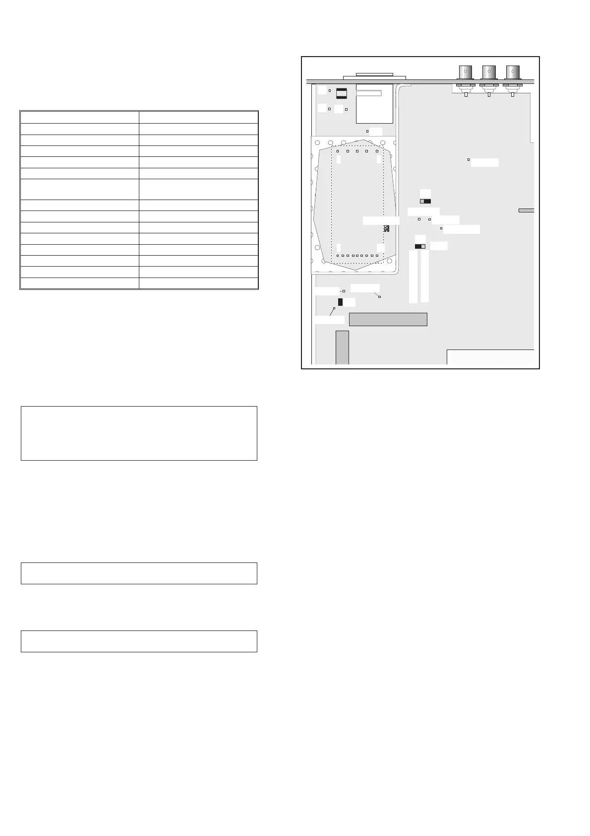
Connect the DMM to test point TP15 = +5V and GND, (see
Fig. 6-2).
–
Adjust the +5V trim potentiometer inside the power module
until the DMM reads +5.10 ± 0.01 V.
–
Check that the voltage between the test point TP23 = +5 V and
GND is +5.06 ± 0.03 V.
–
Check that the unregulated voltage from the power module at
test point TP16 = +15 V is about +18 V.
–
Check that the unregulated voltage from the power module at
test point TP17 = –7 V is about –8 V.
–
Reinstall the protective cover onto the power module.
6-2 Introduction
Power
Module
Fuse
TP23, +5
TP20, -5.2
TP22, +7
J10
J9
J4
J3
+5V adjust
6 14
1 5
TP21,+12V
TP15, +5
TP17, -7
J15
TP16, +15
Load
Disconnected
Connected
J21
J16
Fig. 6-1 Test points and trimmer for the Power Supply.
Type Performance
DMM Acc. 0.02% / Res. 1mV
HF synthesizer 3300 MHz
Pulse generator 125 MHz/2nsrise/fall time
LF synthesizer 50 MHz / 20 Vpp
Oscilloscope 300 MHz / 2-channel
Passive probe 10:1, preferably 500 W (or well
compensated 10 MW)
FET probe 300 MHz
Power supply 12V/2A
Power splitter 50 W /4W
Feed-through termination 50 W
10 MHz reference 1x10
-7
10 MHz reference 1x10
-9
*
BNC-BNC cables Different lengths
Screwdrivers Torx 10 & 20
Table 6-1 Required test equipment.