Hardware Functional Description
Front Unit
LCD Drivers
An LCD and two LEDs are used as indicators. The LCD is used to
show both the measurement result and the state indicators of the in
-
strument setting. The LEDs show standby and gating.
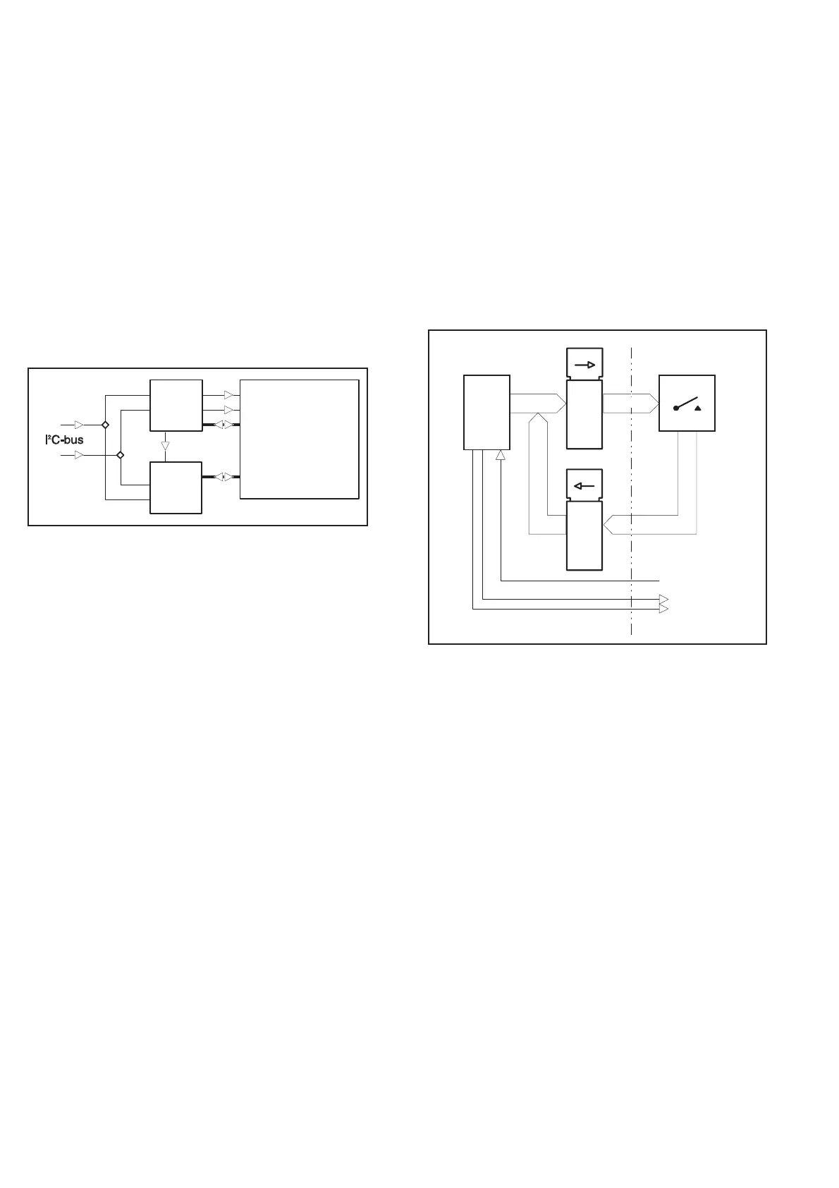
The LCD has 158 segments that are multiplexed with a ratio of 2:1.
Two parallel and synchronized LCD drivers (U201 and U202) are
used. They are connected with a serial I
2
C bus to the microcomputer
on the main board. The clock frequency of the drivers is approxi
-
mately 140 kHz, set by R201. The VLCD pin is connected to GND
on the main board.
The LCD is provided with a backlight, an LED array integrated into
one component. Its current consumption is set by the resistors
R204-R207. The backlight dissipates approximately 1.5 W .
Keyboard
The front panel pushbuttons are connected in a matrix. The scanning
signals H0 to H3 come from the main board. If a push button is
pressed and H0 to H3 is high, one of the output signals V0 to V7 will
be high. The STAND-BY/ON and LOCAL-PRESET buttons are not
part of the scanning but are connected directly to the main board.
The front unit is fixed to the main board unit with three screws. The
electrical connection is made with a 40-lead flat cable to the main
board.
4-4 Hardware Functional Description
U2 02
Driver 2
PC F8576
LC D
U201
Driver 1
PC F8 576
Sync.
SCL
SDA
Backpl. 0
Backpl. 1
2:1 Multiplex
1 58 segment s
Fig. 4-2 Front panel LCD drivers.
V0-V7
AD0-AD7 H0-H3
AD0-AD7
U11
U13A
U14A
LOCAL/PRESET
SDA
SCL
Main Board
Keyboard & Display
Board
CPU
HS1.0
P1.0
P1.1
Latch
Latch
Fig. 3 Keyboard scanning.