–
Observe that the level displayed on the CRO B channel for
Pin 10 of U8 is now approximately 120 mV
pp
, indicating that
the x11 Attenuator has been selected.
Trigger Levels
n
Setup
–
Disconnect all input signals to the counter.
n
Zero levels
Channel A
–
Connect the DMM to test points TP10 = TRIG LEVEL
COMP I and GND = screen.
–
Adjust R69 = ZERO ADJ COMP. I until the DMM reads
+0.95 ± 0.05 mV.
–
Connect the DMM to test points TP11 = TRIG LEVEL
COMP II and GND=screen.
–
Adjust R70 = ZERO ADJ COMP. II until the DMM reads
–0.95 ± 0.05 mV.
Sensitivity
n
Setup
–
Measure the DC voltage between test points TP26="–" and
TP27="+", (see Fig. 6-2).
–
Adjust R91 = SENSE until the DMM reads 10 ± 0.2 mV.
Offset
n
Setup
–
Connect the Signal generator to the A input of the counter.
–
Press NULL on the counter.
–
Decrease the amlitude from the signal generator to
–28 dBm.
–
Adjust R33 = OFFSET A until the counter reads < ±100 Hz.
–
If this is not possible, adjust R91= SENSE until the counter
reads < ±100 Hz.
NOTE: Reinstall the screen shield after making these adjust
-
ments.
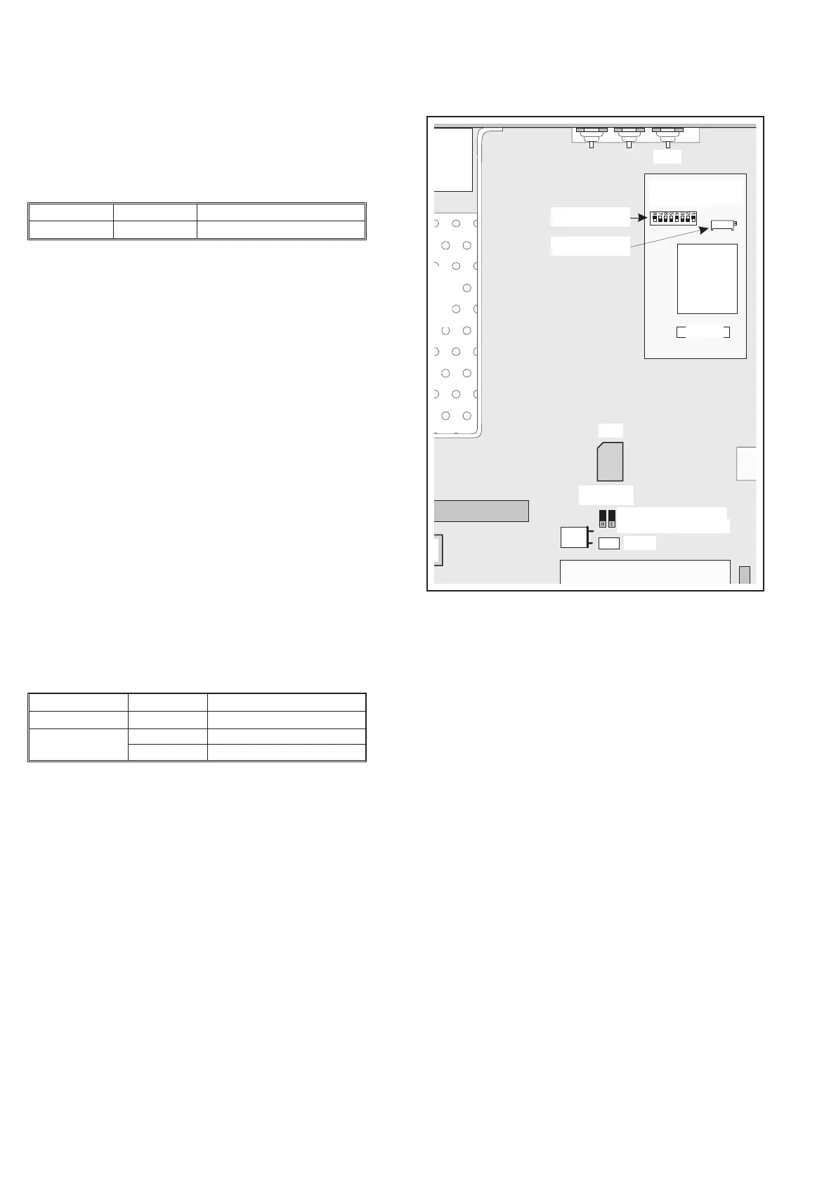
Reference Oscillators
NOTE: The standard oscillator is always mounted in the unit,
even if an optional oscillator is installed. You set the
jumpers J23 and J25 to select the timebase source
that you want to use.
Standard Oscillator
n
Setup
–
Connect the counter to line power.
–
Switch on the counter.
–
Press PRESET, then press ENTER.
–
Connect the 10 MHz reference to the A input of the counter.
–
Press CHECK, NULL, and CHECK again.
The adjustment should preferably be made at an ambient tempera
-
ture of +23 °C.
n
Adjustment
–
Adjust C115 = STD OSC ADJ, until the counter reads
10 MHz ± 5 Hz.
NOTE: Move the two jumpers J23 and J25 back to position
OPT if an optional oscillator is installed.
6-4 Reference Oscillators
PM6685
Impedance 50 W
Sensitivity 10 mV
rms
Signal generator
Amplitude –18 dBm
Frequency 50 MHz
Table 6-5
PM6685
Impedance 50 W
Sensitivity 10 mV
rms
Table 6-6
U29
Standard oscillator
C115
B2
J24
Optional OCXO
Optional oscillator
J23 J25
31
81
1
51
Coarse adjust
Fine adjust
J27
Fig. 6-3 Trimmers for the reference oscillator frequency.