Oven-Controlled Oscillators (OCXO),
PM9691 & PM9692
PM9691 is adjusted to 10 MHz ± 0.2 Hz when manufactured,
PM9692 to 10 MHz ± 0.05 Hz, so there is no need to adjust the fre
-
quency directly after installation.
These oscillators, like any oscillator, change frequency because of
aging. Use the table in the User’s Handbook, Chapter 11, to calculate
when calibration is due. The complete specifications can be found in
the same manual, Chapter 12.
Required test equipment
n
Setup
–
Connect the counter to the line power.
–
Switch on the counter.
–
Set the counter to default settings (preset).
Make the adjustment at an ambient temperature of +23 °C, if possi
-
ble. The oscillator must have been operating continuously for 48
hours before an adjustment.
–
Connect the 10 MHz OUT socket of the counter to be adjusted
(rear panel) to the Input A of the PM6681R/PM6685R.
–
Set up the PM6681R/PM6685R:
–
Measuring time = 0.5 s
–
50 W input impedance
–
Frequency A measurements
n
Adjustment
The oscillator has a voltage controlled adjustment range. This range
is divided into five fixed steps set via DIP switches, and a trimmer to
fine tune the control voltage.
Normally the range of the trimmer should be sufficient to compen
-
sate for the aging that occurs during at least two years of operation.
Fine adjustment
–
Adjust the trimmer to better than 10 MHz ± 0.2 Hz (PM9691)
or 10 MHz ± 0.05 Hz (PM9692), i.e. ±20 resp. ±5 in the last
two digits on the PM6681R/PM6685R display.
–
If this adjustment is OK, reassemble the counter.
Coarse adjustment
Make this adjustment only if the trimmer range is insufficient to ad
-
just the oscillator.
–
Remove the tape from the DIP-switch.
–
Adjust the trimmer to its mid position (about 12 turns from ei
-
ther end position).
Read the frequency on the PM6681R/PM6685R.
(Nominal 10.000000 MHz).
–
If the frequency is too low, set the DIP-switches to the next
higher voltage range.
–
If the frequency is too high, set the DIP-switches to the
next lower voltage range.
NOTE: There are also oscillators that do not have DIP
switches. If this is the case, then the trimmer potenti
-
ometer alone covers the whole adjustment range.
Reference Oscillators 6-5
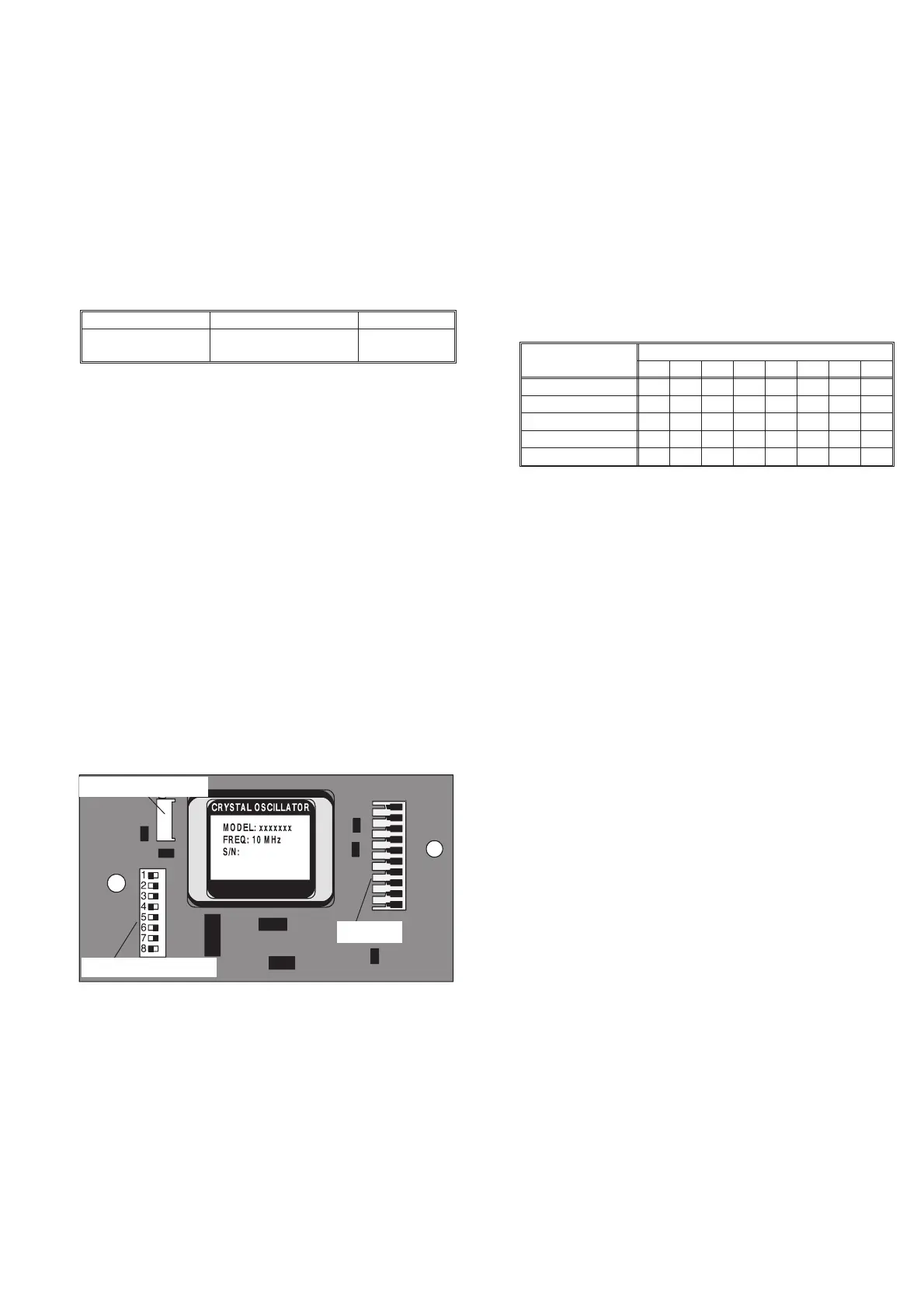
Fig. 6-4 Adjusting the optional oscillator frequency.
Connector
Trimmer for fine tuning
Switches for coarse adj.
Instrument Required specification Model
Counter with Rubidium
Reference
10 MHz ± 0.01 Hz (Uncer
-
tainty £ 1x10
-9
)
PM6681R or
PM6685R
Table 6-7
Trimmer range (V) DIP switch number (1 = on, 0 = off)
12345678
2.6-3.4 00 01 00 00
3.2-3.9 01 01 10 00
3.5-4.3 10 01 10 00
4.0-4.7 10 11 11 00
4.1-5.0 10 10 11 10
Table 6-8