Safety Components
Components in the primary circuits are important to the safety of the
instrument and may be replaced only by components obtained from
your local Fluke organization.
Check the Protective Ground Connection
Visually check the correct connection and condition and measure the
resistance between the protective lead at the plug and the cabinet.
The resistance must not be more than 0.5 W. During measurement,
the power cord should be moved. Any variations in resistance shows
a defect.
Calibration Adjustments
Required Test Equipment
Preparation
WARNING: Live parts and accessible terminals which
can be dangerous to life are always exposed inside
the unit when it is connected to the line power. Use
extreme caution when handling, testing, or adjust
-
ing the counter.
Before beginning the calibration adjustments, power up the instru
-
ment and leave it on for at least 60 minutes to let it reach normal oper
-
ating temperature.
n
Setup
–
Connect the counter to the line power.
–
Switch on the counter.
–
Press PRESET, then press ENTER.
n
Adjustment
CAUTION: If you adjust the +5 V trimmer you have to
adjust the complete instrument.
–
Connect the DMM between TP23 and ground, see Fig. 9-11.
–
Adjust the +5 V trimmer potentiometer R50 in the power sup
-
ply through the nearest vent in the protective cover, until the
DMM reads +5.00 ± 0.01 V.
–
Check that the unregulated voltage from the power supply at
test point TP16=+15 is about +18 V.
–
Check that the unregulated voltage from the power supply at
test points TP17=–7 is about –8 V.
Calibration Adjustments 9-7
Type Performance
DMM 3.5 digits
Table 9-3 Required Test Equipment.
0.2
0.4
0.6
0.8
1.0
1.1
1.2
V
2
4
6
8
10
12
V
1
2
3
V
2
4
6
8
10
12
V
100
200
300
400
V
500
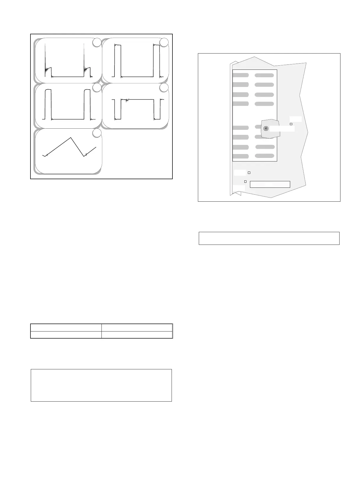
V0 1 G a t e
V01 drain
U0 3 p i n 7 R C
U03 pin 10 OUT
V01 S ource ( current )
024 8610uS
024 8610uS
024 8610uS
024 8610uS024 8610uS
A
C
B
D
E
Fig. 9-10 Typical curves of the power supply.
Power
Modu le
TP16
TP17
TP23
J1 8
+5V adjust
Fig. 9-11 Test points and trimmer for the power supply.