Other Options
HF Input 3.0 GHz , PM9624
NOTE: Before beginning any adjustments, the HF input must
have been in operation for at least one minute to let it
reach normal operating temperature.
n
Setup
–
Connect the counter to line power.
–
Switch on the counter.
–
Press PRESET, then press ENTER.
–
Connect the signal generator to the HF input.
n
Adjustment
–
Turn the potentiometer R61, (see Fig. 6-5) fully counterclock-
wise.
–
Check that the GATE indicator stops blinking.
–
Turn R61 slowly clockwise until the GATE indicator starts
blinking.
The input frequency, 800 ± 25 MHz, will now be displayed.
To verify the 3.0 GHz HF input, a sweep frequency synthesizer is
needed. Also refer to Chapter 2 - Performance Check: Options,
Prescaler.
GPIB Interface, PM9626B
n
Setup
–
Connect the counter to line power.
–
Switch on the counter.
–
Press PRESET, then press ENTER.
–
Connect the DMM to the BNC output of the analog output.
–
Activate the analog output.
–
Select AUX MENU.
–
Press DATA ENTRY UP/DOWN keys until the display
reads ANALOG OUT.
–
Press ENTER.
–
Press DATA ENTRY UP/DOWN keys to select ON.
–
Press ENTER.
–
Press DATA ENTRY UP/DOWN keys to until the display
reads 1.0
-3
V.
–
Press ENTER.
–
Connect the LF synthesizer to the A input of the counter.
The counter should read 1000.0xxxxx Hz.
n
Adjustment
–
Adjust the trimmer ZERO (see Fig. 6-6) until the output volt
-
ageis0V±1mV.
–
Set the LF synthesizer to 999.90 Hz/1V
pp
square wave.
The counter should read 999.9xxxxx Hz.
–
Adjust the trimmer FULL SCALE (see figure 6-6) until the
output voltage is 4.980 V±3mV.
–
Set the LF synthesizr to 100.01 Hz/1V
pp
square wave.
The counter should read 100.0xxxxxx Hz.
–
Check that the output voltage is 500 mV±5mV.
6-6 Other Options
PM6685
Function FREQ C
Signal gener
-
ator
Frequency 800 ± 25 MHz
Amplitude 5.9 ± 0.5 mV
rms
Table 6-9
HF input
J19
R61
TP1
TP9
Fig. 6-5 Test points and trimmers for the 3.0 GHz HF
input.
U109
U101
U106
BU101
U103
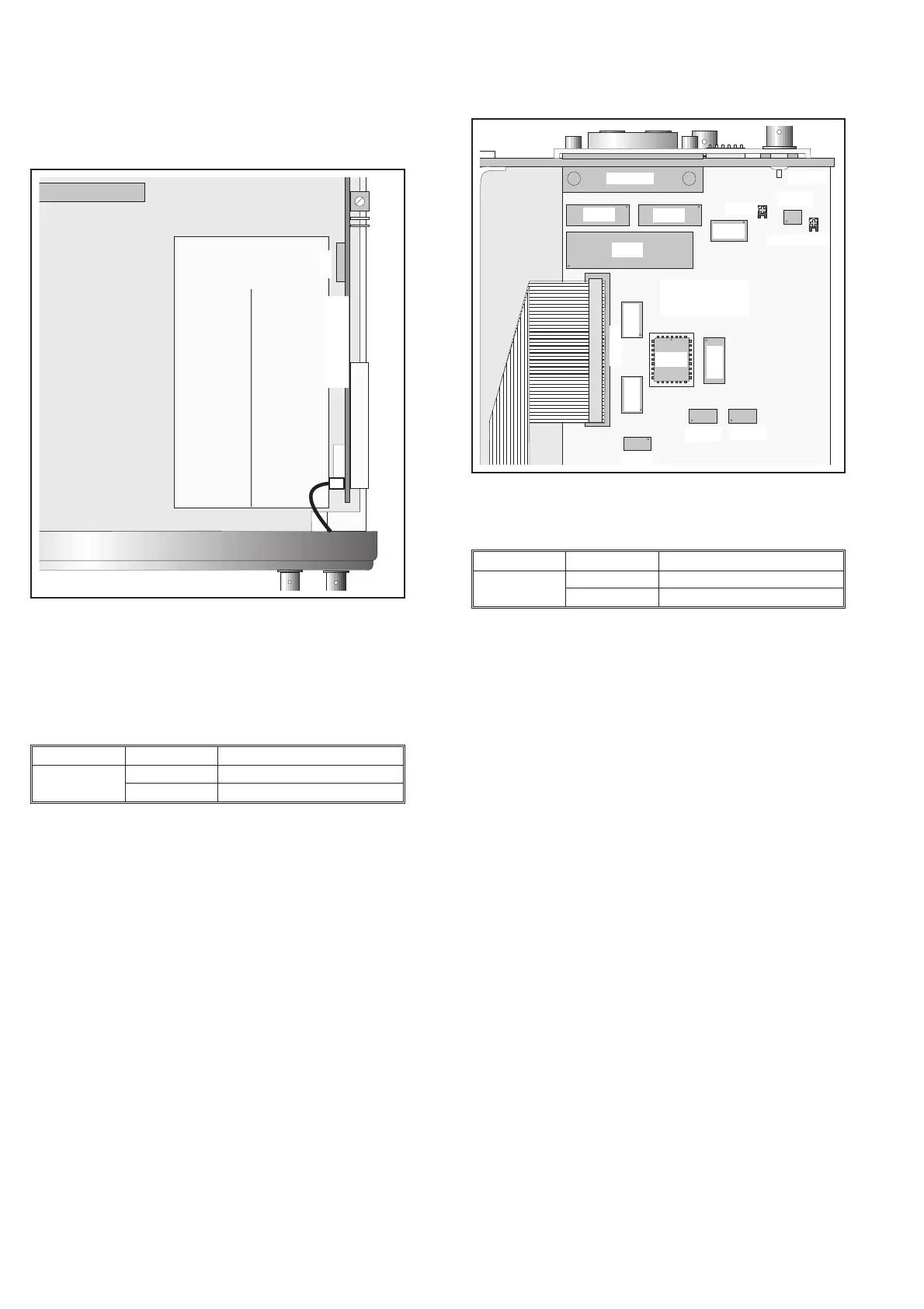
Zero
GPIB
BU102
BU103
Full Scale
U107
U111
U108
U113
U116
U114
U115
Fig. 6-6 Trimmers for the GPIB interface.
PM6685
Input A 50 W / AC / Manual trigger levels
LF synthe
-
sizer
Amplitude 1V
pp
Period 1000.01 Hz square wave
Table 6-10