Keyboard Test
The keyboard test verifies that the counter responds when you press
any key. To check the function behind the keys, see the tests further
on in this chapter.
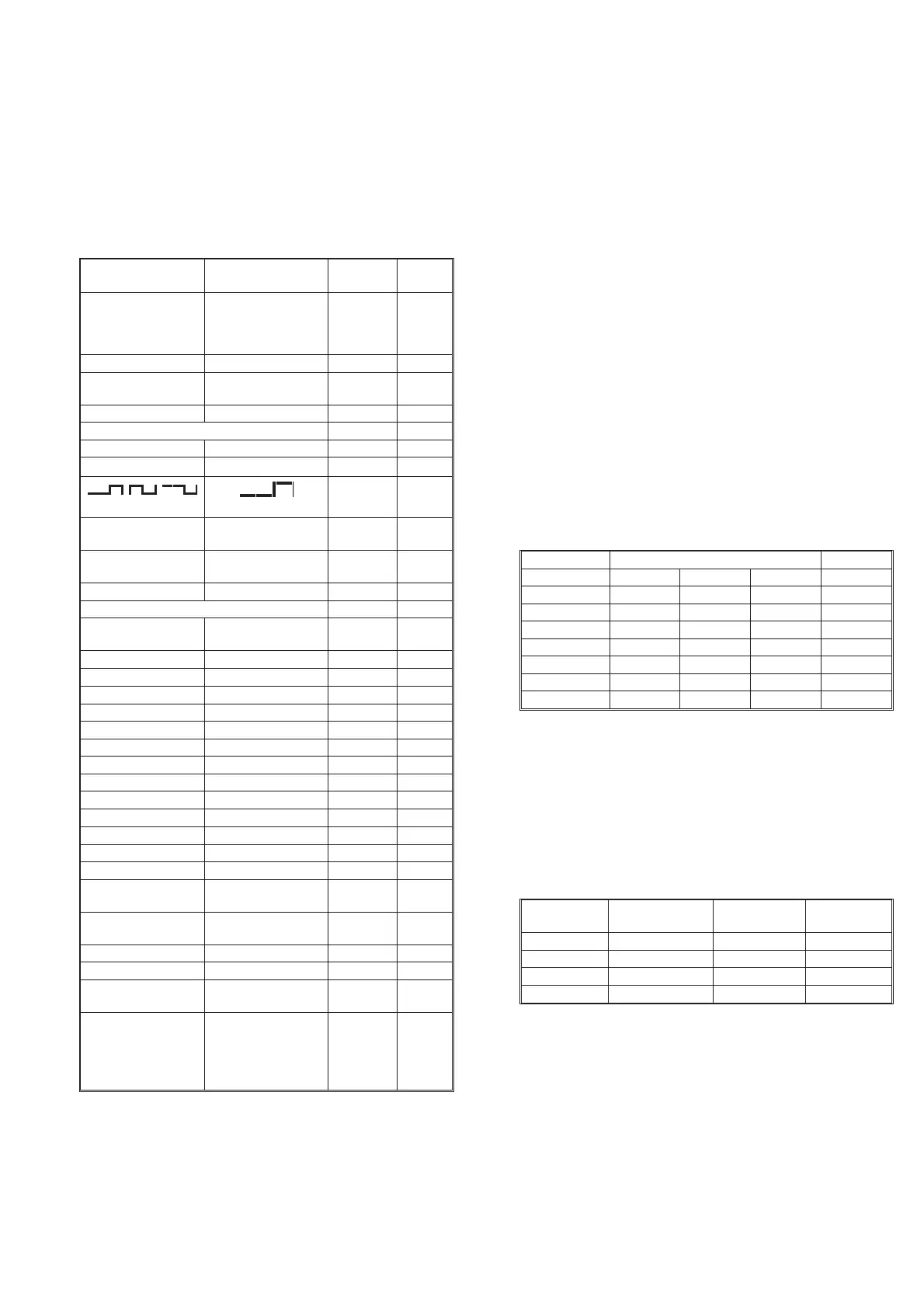
Press the keys as described in the left column and look on the display
for the text, as described in the second column. Some keys change
more text on the display than described here. The display text men
-
tioned here is the text mainly associated with the selected key.
NOTE: For the instrument to respond correctly, this test must
be carried out in sequence and you must start with the
preset (power-on) setting.
* The LSD may vary.
** MENU is not disabled by setting DEFAULT; press menu again.
Short Form Specification
Test
Sensitivity and Frequency Range
–
Press the PRESET key to set the counter in the default setting.
Then confirm by pressing ENTER.
–
Turn off AUTO.
–
Select IMP A = 50 W and maximum sensitivity.
–
Connect a signal from a HF generator to a BNC power splitter.
–
Connect the power splitter to your counter and an oscilloscope.
–
Set input impedance to 50 W on the oscilloscope.
–
Adjust the amplitude according to the following table. Read
the level on the oscilloscope. The counter should display the
correct frequency.
Reference Oscillators
X-tal oscillators are affected by a number of external conditions,
such as ambient temperature and supply voltage, but they are also af
-
fected by aging. Therefore, it is hard to give limits for the allowed
frequency deviation. You must decide the limits depending on your
application, and recalibrate the oscillator accordingly. See the Pre
-
ventive Maintenance in the Repair chapter, Chapter 5.
To check the accuracy of the oscillator you must have a calibrated
reference signal that is at least five times as stable as the oscillator
that you are testing, see the following table.
–
Press the PRESET key, then press the ENTER key to set your
counter in the Default setting.
Performance Check, Short Form Specification Test 2-3
Key(s) Display Note Pass
/Fail
STAND-BY Display Off Red LED
beside
the key
On
ON Backlight on
PRESET
ENTER
DEFAULT?
NO SIGNAL
Default
setting
EXT REF EXT REF
Input A
FILTER FILTER
50 W
50 W
(2 times)
SENS
(2 times)
Bar graph:
zzzzzzzz
SENS
(2 times)
Bar graph:
zzzzzzzzzz
AUTO AUTO TRIG
Other
PRESET
ENTER
DEFAULT?
NO SIGNAL
Default
setting
MEAS TIME 200
–3
s
DATA ENTRY 500
–3
s
DATA ENTRY 200
–3
s
ENTER NO SIGNAL
DISPLAY HOLD HOLD
DISPLAY HOLD
SINGLE SINGLE
FUNCTION DUTY F A
FUNCTION TOT A MAN
FUNCTION DUTY F A
FUNCTION FREQ A
AUX MENU RECALL
MEAS RESTART NO SIGNAL
PRESET
ENTER
DEFAULT?
NO SIGNAL
Default
setting
CHECK 10.00000000
6
Hz* Start
counting
NULL NULL
NULL 10.00000000
6
Hz*
BLANK DIGITS
(3 times)
10.00000___
6
Hz*
MENU Displays all avail
-
able functions, pro
-
cesses and input
controls. Selected
items are blinking.
Table 2-2 Keyboard Test.
Frequency Level Pass/Fail
MHz mV
PP
mV
RMS
dBm Input A
1 30 10 –27
25 30 10 –27
50 30 10 –27
150 60 20 –21
200 90 30 –17
250 150 50 -13
300 150 50 -13
Table 2-3 Sensitivity of input A at various frequencies.
Oscillator Max. tempera
-
ture dependence
Max. aging
per month
Max. aging
per year
Standard ±100 Hz ±5 Hz ±50 Hz
PM9691 ±0.05 Hz ±0.1 Hz ±0.75 Hz
PM9692 ±0.025 Hz ±0.03 Hz ±0.2
Rubidium ±0.003 Hz ±0.0005 Hz ±0.002 Hz
Table 2-4 Deviation (for PM9691 and PM9692 after a
warm-up period of 48 hours).