–
The STAND-BY button is connected to the ON/STANDBY
logic in the power supply.
–
The LOCAL/PRESET button is connected directly to input pin
24 on the microcontroller U11. Pressing this button sends an
interrupt to a special handler in the SW.
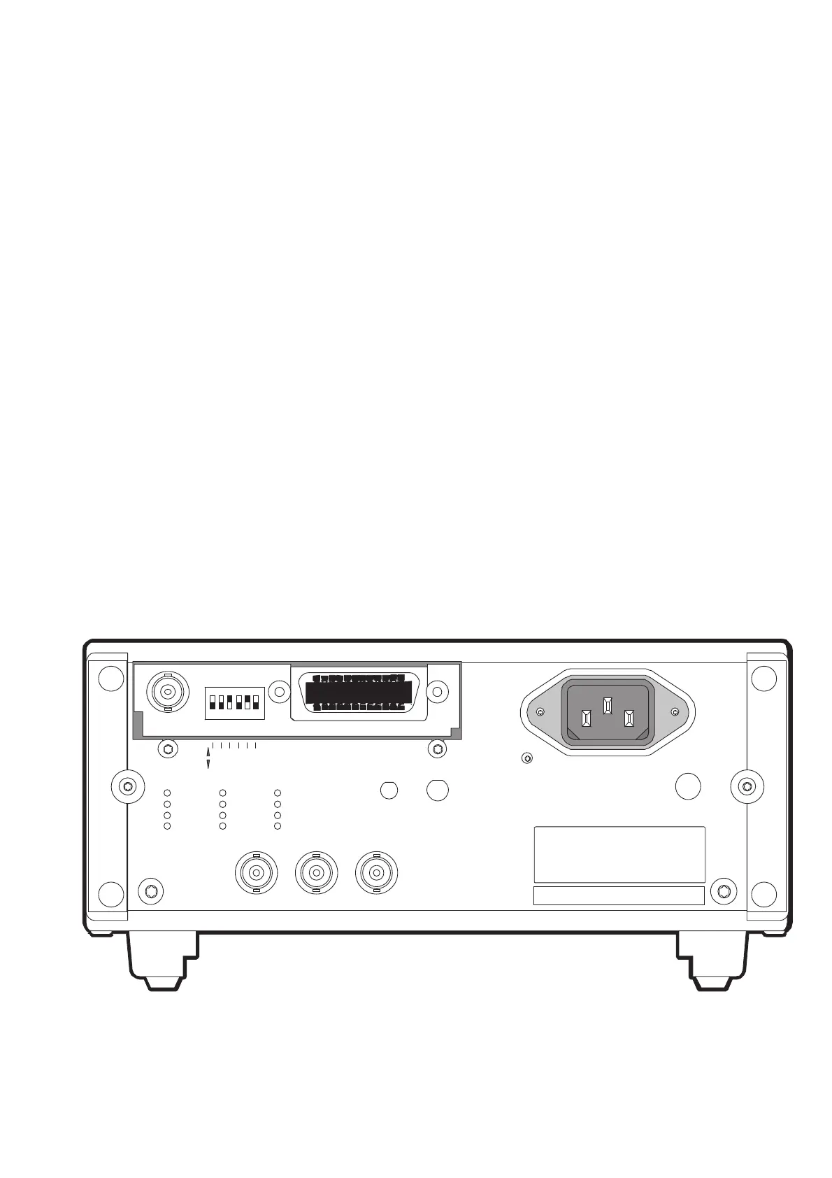
Rear Panel Unit
The rear panel contains the following connectors
INPUTS:
–
External reference input D - REF IN (BNC)
–
External arming input E - EXT ARM (BNC)
–
Power supply inlet including EMI filter
OUTPUTS:
–
Internal reference output G - 10 MHz OUT (BNC)
If a GPIB interface is installed in the device, it is mounted on the rear
panel and connected to the main board with a flat cable.
Besides the normal standard GPIB connector, this optional unit also
has a BNC connector capable of outputting an analog representation
of any three consecutive digits on the display.
There is also a 6 SPST DIP switch on this unit for setting the default
GPIB address.
Hardware Functional Description 4-13
OF F
ON
GDE
168 421
RL1,DC1, DT 1, E2
SH 1, AH1, T 5, L4, SR1,
I E E E 4 88 / I E C 62 5 I NT ER F A CE
A DDRE S S
90 V - 26 5V
1.6AT
PRIMA RY FUSE
INSIDE
-I NT -ST BY
BAT T ERY
ANALOG OUT
10M Hz O UT REF IN E XT AR M
P M962 1
P M962 3
P M962 4
P M962 5
PM9626
PM9678
PM9690
PM9691
PM9 628 /85
_______
_______
P M9697
-EX T /L I NE
POWE R
EXT SUPPLY
12-24V DC
Fig. 4-14 Rear panel.