Troubleshooting
General
Quick Troubleshooting
The PM6685 is a highly integrated Frequency counter with dedicated
LSI counter circuits and microcontrollers that control the complete
units. The microcontroller can help you locate faulty parts by run
-
ning test programs and generating stable signal patterns on t
he bus. If the microcontroller does not work or the fault is in a part of
the counter that cannot be accessed by the microcontroller, tradi
-
tional troubleshooting must be performed.
Where to Start
After reading the safety instructions, continue with this chapter for
troubleshooting and repair instructions. When you have fixed the in
-
strument, always do the Safety Inspection and Test after Repair, as
described later in this Chapter. Then do the checks in Chapter 2, Per
-
formance Check. Recalibrate if required by following the adjustment
instructions in chapter 6, Calibration Adjustments.
Logic Levels
The PM6685 contains logic of four families. The levels for these
families are listed in the following table.
Required Test Equipment
To test the instrument properly using this manual, you will need the
equipment listed below. The list contains specifications for the criti
-
cal parameters.
PROM Identification
There are two different PROMs in the PM6685, one on the main
PCB containing the instrument firmware, the other on the optional
GPIB board, containing the interface bus firmware.
They have labels with version designation of the traditional form
Vx.yz, where x, y, and z are digits. The last digit can be followed by a
single letter. The version numbers do not have to coincide, except for
the last letter. So the combination Vr.stE and Vu.vwE is valid,
whereas Vr.stE and Vu.vwF is not.
Operating Conditions
Power voltage must be in the range of 90 to 260 VAC.
Introduction
The troubleshooting strategy for the PM6685 is an integrated part of
the overall service strategy for the instrument. This instrument is hi
-
5-4 Troubleshooting
Positive
ECL
Negative
ECL
CMOS TTL
Supply voltage +5 V -5.2 V +5 V +5 V
Signal ground 0 V 0 V 0 V 0 V
Input voltage
High, V
IH >+3.9 V >-1.1 V >+4 V >+2 V
Low, V
IL <+3.5 V <-1.5 V <+1 V <+0.8 V
Output voltage
High, V
OH >+4 V >-1 V >+4.9 V >+2.7 V
Low, V
OL <+3.3 V <-1.7 V <+0.05 V <+0.4 V
Bias ref. voltage, V
BB +3.7 V -1.3 V - -
Table 5-2 Logic levels.
Type Performance
DMM
3.5 digits
Oscilloscope 300 MHz 2-channel
Signal generator 3300 MHz
Power supply 12 V/2 A
BNC-BNC 50 W cables RG-58
Table 5-3 Required test equipment.
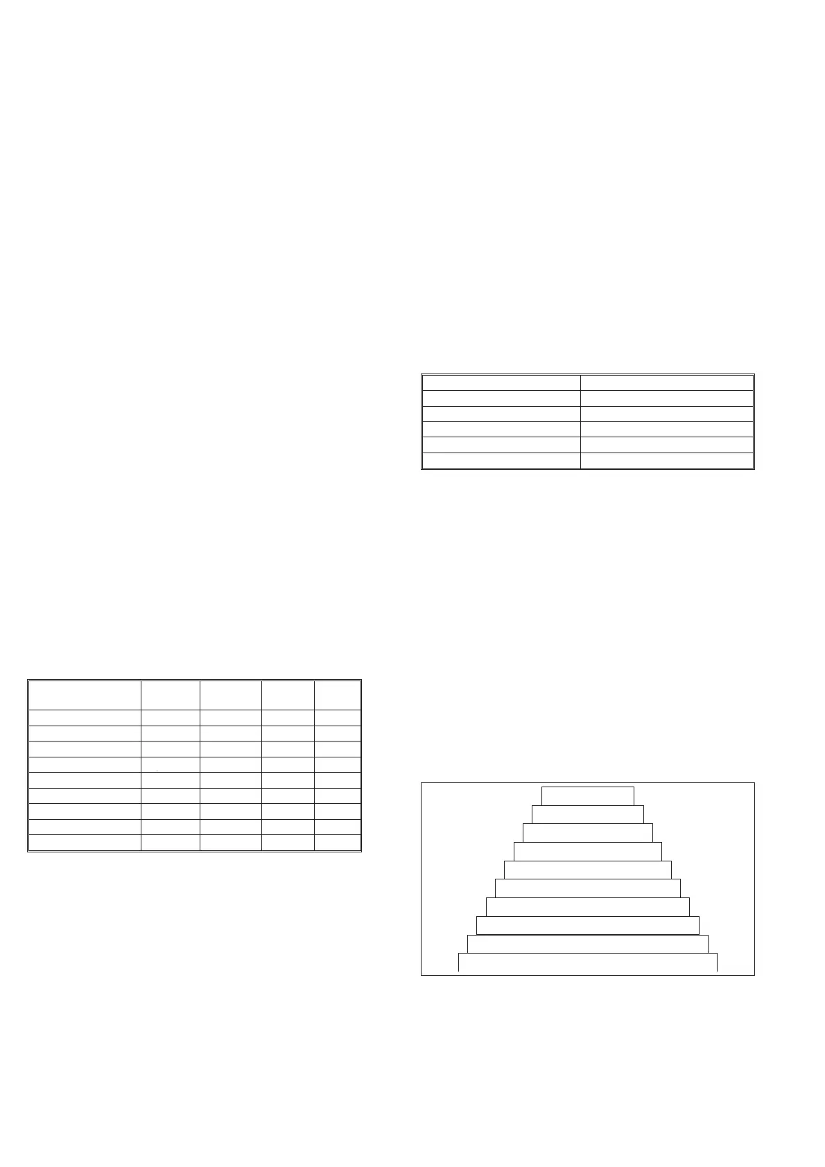
I N P U T A M P LI F I E R ( L ev el 9 )
D / A C O N V E R TE R S (L ev el 8 )
MEASU RI NG LOG IC(Le vel7 )
KEY BOARD (Level6 )
I NTE RN A L CO NT R O L S I G NAL S & DIS PLA Y (L ev el 5 )
MICROCO MP UT ER KERNEL (Level 4)
MICROCONTROLLER (Level 3)
OSCILLA TOR(Level 2)
POWE R SUPPLY ( Le vel 1)
GPIB(Level 10)
Fig. 5-1 Functional levels.