erarchically designed in different levels, and troubleshooting can be
performed in any design level if the lower levels are OK. It is, there
-
fore, important to disconnect all options at the beginning of the trou
-
bleshooting procedure.
Power Supply
Connect the counter to line power.
–
Set the counter to STAND-BY mode.
–
Check that the voltage between J9 and J10 is in the range of
90 to 260 VAC, (see Fig. 5-2).
–
Check that the input voltage to the power module, U39 be
-
tween pin 1 and pins 4 and 5 on the bottom side of the PCA, is
120 to 375 VDC.
–
Move the jumper J16 to the DISCONNECT position.
–
Check the “STAND BY” voltages after the power module,
U39. Use for instance the screen around the input amplifier as
ground connection. There are also a number of ground pads on
the PCB available for this purpose.
*NOTE: If this voltage does not meet the above-mentioned
spec, and if it is not possible to adjust it, the output
resistances of the module must be checked.
To verify the Power Module proceed as follows:
–
If the primary fuse is broken, there is a short circuit in the
primary circuits. Use a DMM and try to locate the fault by
resistance measurements.
–
Disconnect L6 and check the resistance between pin 1 and
pins 4 and 5 on the power module. The DMM should not
show a short circuit. Put L6 back.
–
Check that the DC voltage between pin 1 and pins 4 and 5
on the power module is about Ö 2 times the input
AC-voltage. If not, use traditional troubleshooting tech
-
niques to locate the fault.
–
Remove the power cable from the counter.
–
Measure the resistances according to the table below.
–
If one of the above-mentioned measurements shows 0 W,
remove L7, L8, and L9 and use conventional troubleshoot
-
ing techniques to isolate the fault.
–
Measure the resistances according to the table below.
If the resistances deviate considerably from the values in the table,
the complete power module must be replaced.
–
Move jumper J16 to the CONNect position.
–
Connect the power cable to the counter.
–
Switch the counter ON.
–
Check the “POWER ON” voltages.
*NOTE: If the +5 V voltage is outside the specification, all
other levels will be wrong, since they are based on the
+5 V level.
If you find any fault, continue with traditional troubleshooting tech
-
niques and replace defective circuits. Also refer to Power Supply in
Chapter 4, Circuit Descriptions.
Troubleshooting 5-5
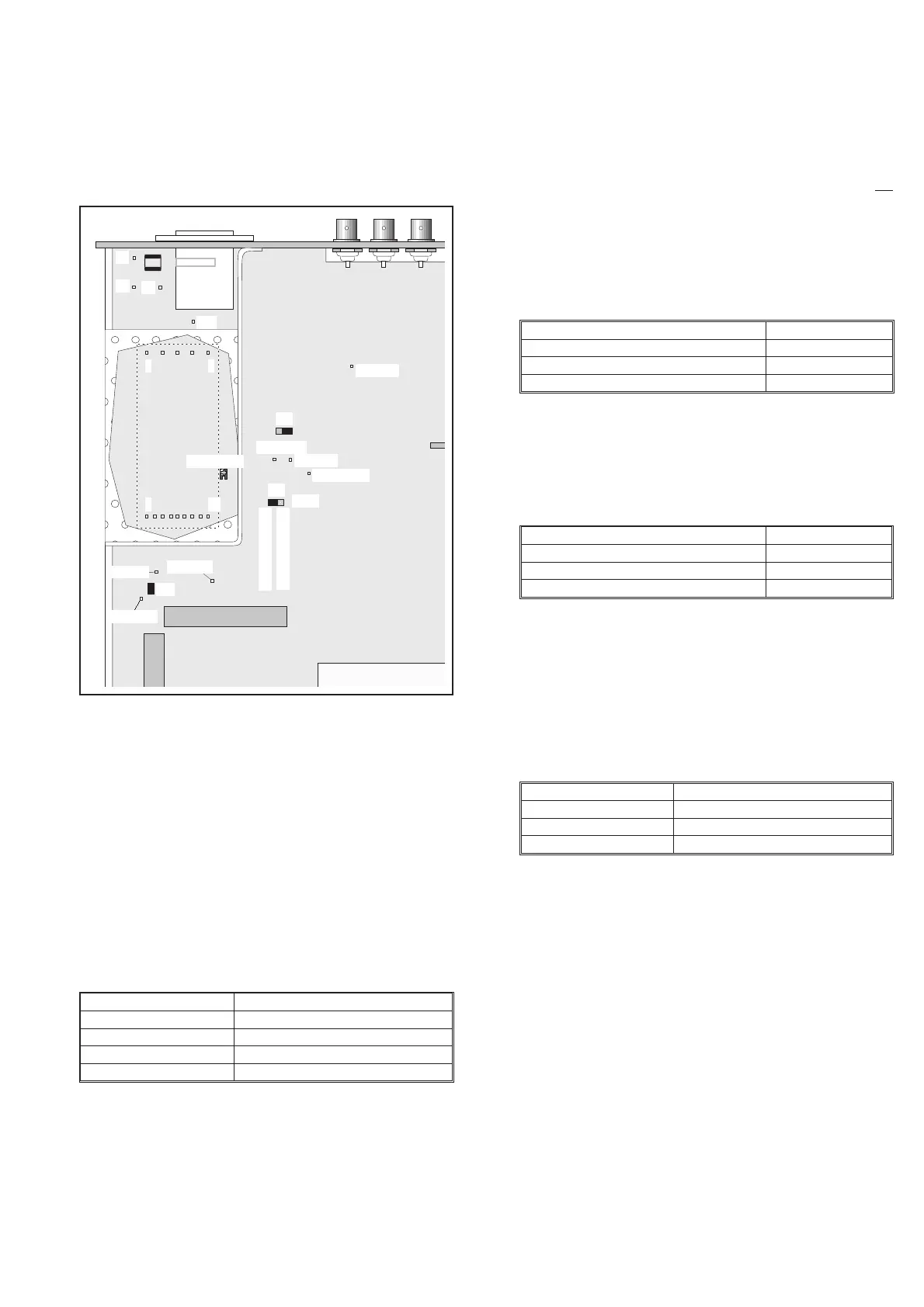
Power
Module
Fuse
TP23, +5
TP20, -5.2
TP22, +7
J10
J9
J4
J3
+5V adjust
6 14
1 5
TP21,+12V
TP15, +5
TP17, -7
J15
TP16, +15
Load
Disconnected
Connected
J21
J16
Fig. 5-2 Test points and trimmers for the power supply.
Test Points Voltage
TP15 +5.10V±10mV*
TP16 +14.8 V to +21 V
TP17 –12.5 V to –7.5 V
TP21 +12 V ± 0.5 V
Table 5-4 Standby voltages.
Test Pins Resistance
(GND) and TP15 (+5 V) »10 W
(GND) and TP16 (+15 V) »1.5 kW
(GND) and TP17 (–7 V) »270 W
Table 5-5 Output resistances.
Test Pins Resistance
10, 11 and 13, 14 »150 W
8 and 9 »1.5 kW
6 and 7 »270 W
Table 5-6 Output resistances.
Test Points Voltage
TP23 +5.06V±30mV*
TP20 –5.2V±50mV
TP22 +7 V ± 100 mV
Table 5-7 Power-on voltages.