Power Supply Switchmode Module
Circuit Descriptions
n
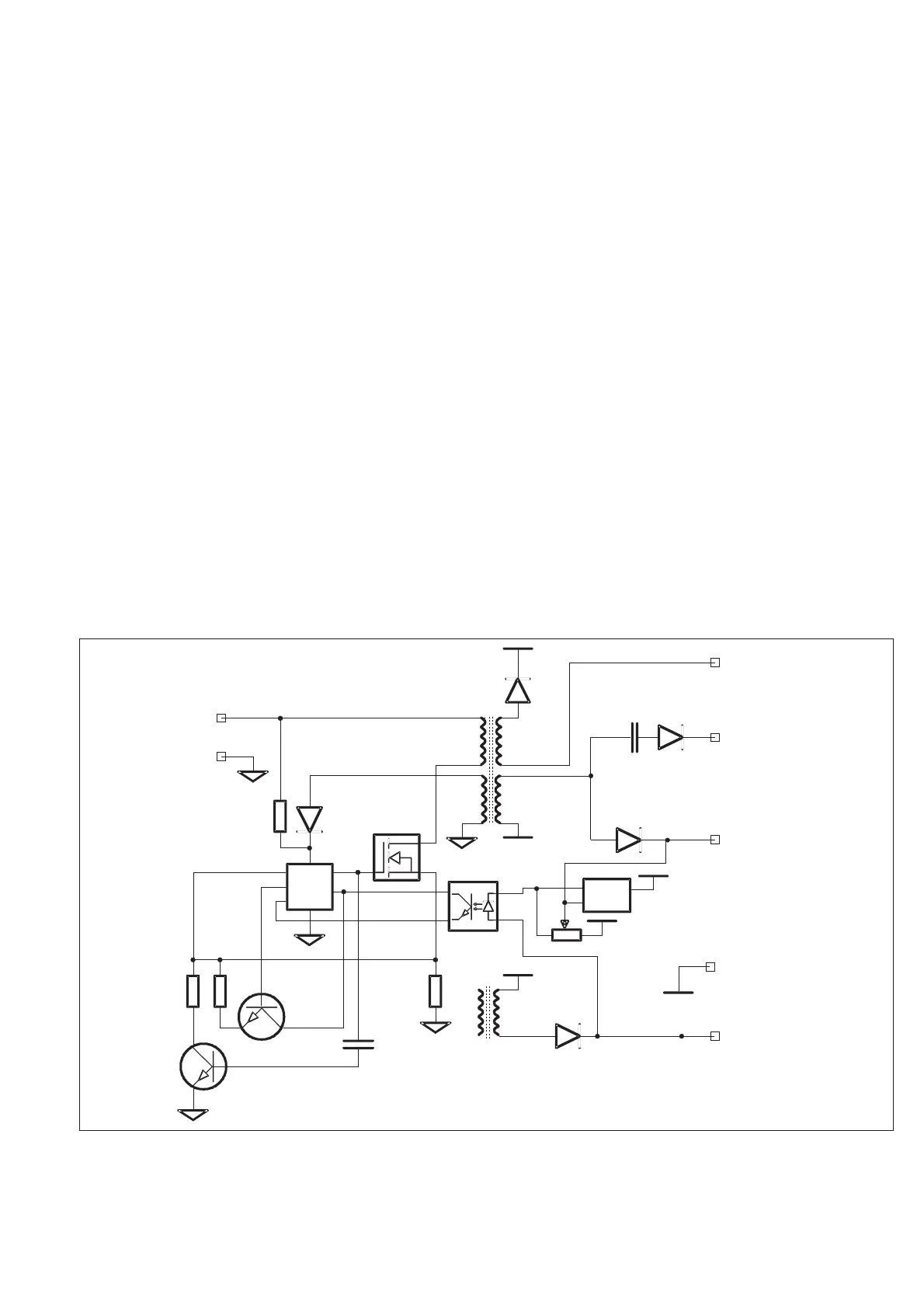
Primary Circuits
For primary circuits outside the power supply module, see Chapter 4,
Circuit Descriptions, Power Supply.
The power supply module generates three DC voltages to the sec
-
ondary circuits.
R24-R27, R31, and R32 give the start-up voltage to the control cir
-
cuit U03. U03 outputs a frequency of 120 kHz on OUT (pin 10) to the
switch transistor V01. When the switch transistor has started, U03
will be supplied from the transformer T01 pin 3 via the diodes D09.
Every switch pulse causes a voltage drop over the resistors R35-R37
and R55. This voltage feeds the SENSE input (pin 5) of the control
circuit U03. When the voltage has reached the internal reference
level in U03, the switch transistor V01 is turned off.
V05 is a blanking transistor that will compensate for high transients
generated by the transformer T01.
The internal sawtooth generator RC (pin 7) in U03 is connected to
the SENSE input via V03, to compensate for low load.
The regulated +5 V is sensed by U01 and adjusted by R50. The out
-
put of U03 is connected to the VF input (pin 3) of U03 via the
optocoupler U02.
The VREF pin (pin 14) outputs a reference voltage of 5 V DC.
n
Secondary circuits
For secondary circuits see Chapter 4, Circuit Descriptions, Power
Supply.
Circuit Descriptions 9-5
P01 pin 1
U02
T01
V01
D09
R24-R27,
R31-R32
V05
V03
U0 3
SENSE
RC
VF
VR EF
OUT
P02 pin 3
P02pin5&6
P02 pin 2
P02 pin 7
R50
U01
D02
D04
D03
T0 1
D01
P01
pin 4 & 5
P02
pin1,4,8,& 9
Fig. 9-8 Power supply module primary circuits.