Optional Units
GPIB Interface Including Analog Output
n
GPIB, PM9626B
The GPIB interface controls the communication between the internal
microprocessor and the external GPIB bus. A 32K extension of the
ROM and RAM is placed on the interface board. An analog output is
also included. The PCB is connected to J18 on the main board with a
ribbon cable and fixed to the rear panel with two screws. Two metal
studs at the rear edge of the PCB are inserted in slots on the main
board in order to relieve mechanical stress.
The GPIB control circuit, IC113, communicates with the external
GPIB bus via the bidirectional bus drivers IC114 and IC115. IC113 is
controlled from the microprocessor by writing and reading in the in
-
ternal control registers. If IC113 has a message for the microproces
-
sor, it uses the GPIB interrupt signal. The address switch setting is
read by the microprocessor via IC116.
A 32K extension of both ROM (IC109 and IC110) and RAM (IC111
and IC112) is placed on the interface board. The circuit board is pre
-
pared for a 16-bit extension, but only 8 bits are used. IC110 (ROM),
IC112 (RAM) and R118 are not mounted. IC107, IC108 are address
latches and IC101, IC106 and IC117 use the latched address to gener
-
ate chip select and chip enable signals for internal use on the GPIB
board.
n
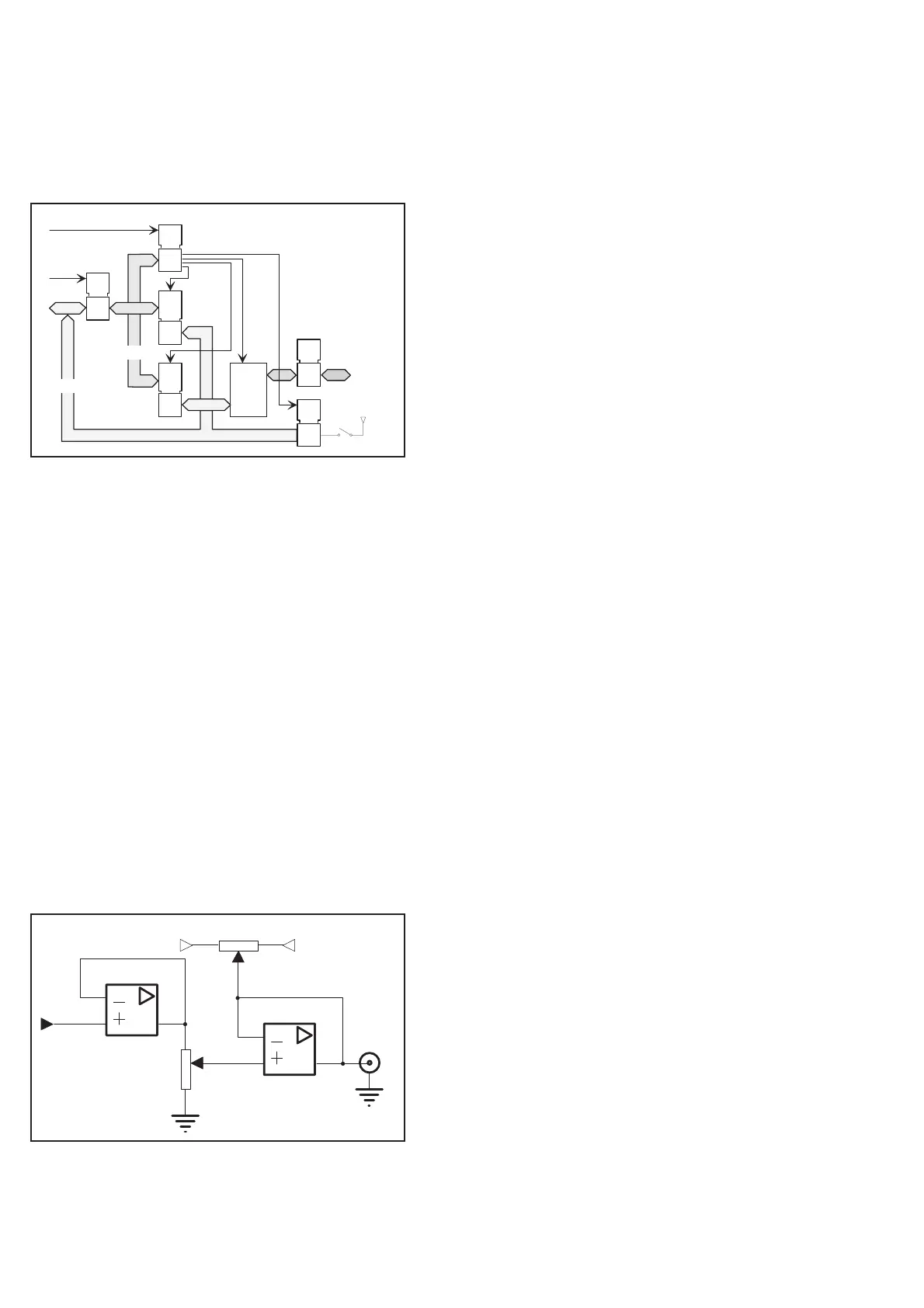
Analog Out
The result on the display can be converted to an analog signal by
means of a pulse-width-modulated (PWM) signal from the micro
-
processor. The signal is filtered, attenuated, offset-adjusted, inte
-
grated and buffered by IC103 and supporting passive components to
give an analog DC level between 0 and 4.98 V with a resolution of
20 mV. The analog output has a separate analog ground connected to
the cabinet.
HF Input
You can add an optional prescaler. This HF input is mounted on the
main board, to the right of the input amplifier. It is connected to J19
where there are three pins reserved for ID coding. Preparations have
thus been made for other prescalers with different prescaling factors.
n
Prescaler 3.0 GHz, PM9624
This prescaler cannot be repaired at a local workshop. It must be sent
to the factory for repair.
The prescaler consists of the following parts:
Limiter
–
The limiter consists ofa6dBattenuator and a PIN diode at
-
tenuator to achieve constant input amplitude to the amplifiers.
Amplifier
–
Five amplifier stages are divided into three blocks. One block
consists of one amplifier. Two blocks consist of two amplifiers
each and an AGC control.
Automatic Gain Control (AGC)
–
Helps the amplifiers retain a constant output amplitude.
Dividers
–
Two dividers divide the input signal frequency by 16.
Detector
–
Detects whether the level of the input signal is high enough to
ensure correct measurement and, if not, blocks the output sig
-
nal from the prescaler.
Positive Voltage Regulator
–
Supplies a well-regulated voltage to the HF amplifiers.
4-14 Hardware Functional Description
IC113
IC101/106/117
IC114/115
IC107/108
IC116
AD0-15
A0-15
+5V
GPIB
connector
IC109/
110
IC111/
112
as
c
oar
Fig. 4-15 GPIB interface.
IC103
IC103
+7V
-5.2V
Analog
Out
PWM
Full scale
Zero
Fig. 4-16 Analog output.